All installations and services must be performed by qualified service personnel.
31
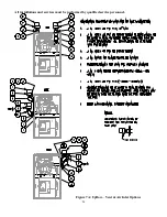
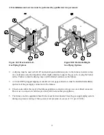
b. Attach tube “C” to the bottom port of the coil outlet. The end of the tube with the label “C” should
be installed on the coil outlet and the other end should be horizontal. On CLQS1-075T42N &
CLQS1-050T36N models, trim tube “C” so that approximately 1” of tubing extends thru the cabinet.
Attach the barb elbow to the end of the tube “C” and attach a piece of clear flexible tubing to the
barb, leading to the drain trap.
c. Trim approximately 1” from the small diameter end of the black tube labeled “B”. Loosen rubber
drain clamp at the exit of inducer and attach tube “B” to the bottom port. The end of the tube with
the label “B” should be installed on the rubber drain and the other end should be horizontal. Rotate
rubber drain so that it points slightly downward, in line with tube “B”, and tighten clamp. Trim tube
“B” so that approximately 1” of tubing extends thru the cabinet. Attach the barb elbow to end of tube
“B” and attach a piece of clear flexible tubing to the barb, leading to the drain trap.
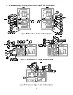
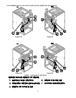
3. DOWNFLOW, see figures 8E.
a. Clear condensate tube to the coil outlet must be moved to the bottom ½” port of the coil outlet.
Move 1/2” cap to the unused coil outlet port.
b. Clear condensate tube to the rubber drain at the exit of the inducer must be moved to the bottom
port of the drain. The plastic internal tube support must also be moved to the bottom port of the
drain.
Condensate lines exit thru the cabinet on left or right, & must slope down to the trap at every point.
c. Black condensate tubing will not be used.
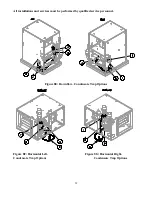
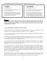
4. HORIZONTAL LEFT, see figure 8F.
a. Attach tube “C” to the bottom port of the coil outlet. The end of the tube with the label “C” should
be installed on the coil outlet and the other end should be vertical. On CLQS1-075T42N & CLQS1-
050T36N models, trim tube “C” so that approximately 1” of tubing extends thru the cabinet. Attach
the barb elbow to the end of tube “C” and attach a piece of clear flexible tubing to the barb, leading to
the drain trap. Move 1/2” cap to the unused coil outlet port.
b. Attach clear flexible tubing from rubber drain at the exit of the inducer thru the cabinet to the drain
trap.
NOTICE:
Condensate trap must be installed at least 2-1/2” below furnace.
5. HORIZONTAL RIGHT, see figure 8G.
a. Inducer must be removed, rotated 180° & re-installed so that vent pipe exits cabinet thru the top.
b. Attach black tube labeled “A” to the bottom port of the coil outlet. The end of the tube with the
label “A” should be installed on the coil outlet and the other end should be vertical. On CLQS1-
100T48N & CLQS1-050T36N models, trim tube “A” so that approximately 1” of tubing extends thru
Summary of Contents for CLQS1-050T36N
Page 2: ......
Page 4: ......
Page 47: ...All installations and services must be performed by qualified service personnel 45...
Page 55: ...All installations and services must be performed by qualified service personnel 53...
Page 56: ...All installations and services must be performed by qualified service personnel 54...
Page 57: ...All installations and services must be performed by qualified service personnel 55...
Page 59: ...All installations and services must be performed by qualified service personnel 57...
Page 60: ...All installations and services must be performed by qualified service personnel 58...

