background image

Refrigeration Diagnosis

147

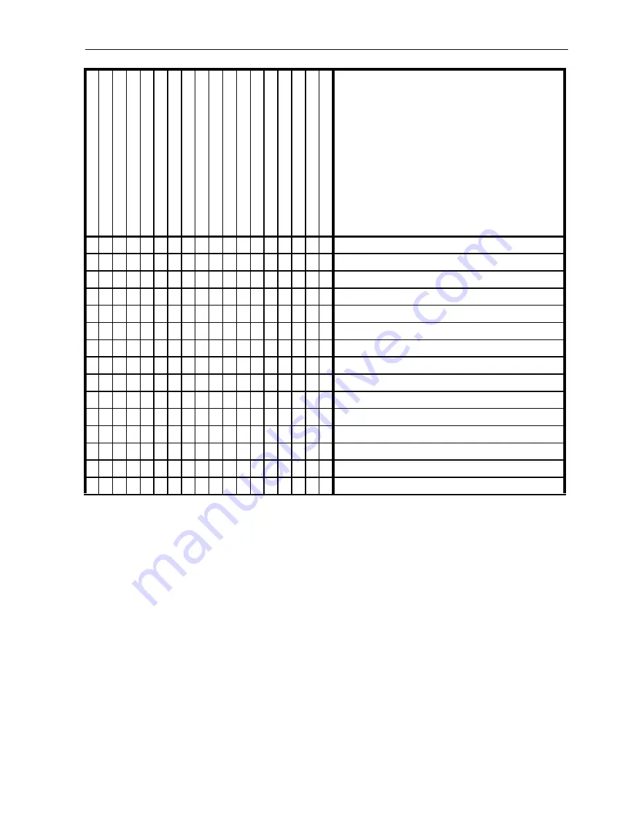
Leaky Zone 1 hot gas solenoid (HGS)

Closed Zone 1 hot gas solenoid (HGS)

Leaky Zone 1 liquid line solenoid (LLS) 

Closed Zone 1 liquid line solenoid (LLS)

Leaky Zone 1 liquid return check vale (LRCV)

Leaky Zone 1 suction line solenoid (SLS)

Leaky Zone 1 suction line check valve (SLCV)

Leaky Zone 2 hot gas solenoid (RHGS)

Closed Zone 2 hot gas solenoid (RHGS)

Leaky Zone 2 liquid line solenoid (RLLS)

Closed Zone 2 liquid line solenoid (RLLS)

Leaky Zone 2 liquid return check valve (RLRCV)

Leaky Zone 2 suction line solenoid (RSLS)

Leaky Zone 2 suction line check valve (RSLCV)

Leaky purge valve (PV)

R

api

d

 c

y

c

ling be

tw

e

en C

o

o

a

nd H

e

a

t

Un

it co

o

ls in

 He

a

a

n

d

 De

fr

o

s

c

ycle

Un

it 

h

e

a

ts in

 r

e

fr

ig

e

ra

tio

n

 c

ycle

H

igh he

ad

 p

re

s

s

u

re

Lo

w he

ad

 p

re

s

s

u

re

N

o

 hea

d pr

es

s

u

re

H

igh s

u

c

ti

on pr

es

s

u

re

Lo

w s

u

c

ti

on pr

es

s

u

re

N

o

 su

ct

io

n pr

es

su

re

U

n

it

 o

p

e

rat

in

g i

n

 a va

c

uum

R

e

c

e

iv

er

 s

igh

t g

las

em

pt

y

S

u

c

ti

on l

in

e

 fr

os

ti

n

g

 ba

ck

U

nab

le

 t

o

 pum

p do

wn

 s

y

s

te

m

Un

a

b

le

 to

 p

u

ll va

cu

u

m

 in

 lo

sid

e

Un

a

b

le

 to

 h

o

ld

 v

a

c

u

u

m

 in

 lo

w s

id

e

No

isy

 co

m

p

re

s

s

o

r

Un

it n

o

re

fr

ig

e

ra

tin

g

U

n

it

 n

o

t hea

ti

n

g

 or

 def

ro

s

ti

n

g

 Sy

mpto

m

Possible Causes

Summary of Contents for MD-MT

Page 1: ...MD MT w TK 3 74 TK 51703 1 MM Rev 0 08 02 Copyright 1999 Thermo King Corp Minneapolis MN USA Printed in USA...

Page 2: ...not responsible and will not be held liable in contract or in tort including negligence for any special indirect or consequential damages including injury or damage caused to vehicles contents or pers...

Page 3: ...ormation on regulations and technician certification programs contact your local Thermo King dealer R 404A WARNING Use only Polyol Ester based refrigeration compressor oil in R 404A See Thermo King Pa...

Page 4: ...4...

Page 5: ...er TG V 26 Unit Operation 27 Reading Mode of Operation Charts 28 Mode of Operation Charts 29 Zone 1 Cool and Zone 2 Cool 33 Zone 1 Cool and Zone 2 Heat 34 Operating Modes 35 Engine Continuous Run Two...

Page 6: ...porator Defrost Cycle Diesel Operation 64 Zone 1 Evaporator Defrost Cycle Electric Operation 64 Zone 1 Evaporator Defrost Cycle Checkout Procedure 65 Zone 2 Evaporator Defrost Cycle Diesel Operation 6...

Page 7: ...Charge 106 Testing the Refrigerant Charge with an Empty Truck 106 Testing the Refrigerant Charge with a Loaded Truck 106 Testing for an Overcharge of Refrigerant 106 Adjusting the refrigerant level 1...

Page 8: ...V RSLCV and PCV 123 Removal 123 Installation 123 In Line Check Valves 123 Removal 123 Installation 123 Receiver Tank Pressure Solenoid Valve RTPS 124 Removal 124 Installation 124 Purge Valve PV 124 Re...

Page 9: ...Unit Protection Devices 155 Serial Number Location 155 Remote Evaporator Refrigeration Service Operations 157 Expansion Valve Assembly 157 Removal 157 Installation 157 Evaporator Coil 157 Removal 157...

Page 10: ...Table of Contents 10...

Page 11: ...ustment 71 Figure 26 Option Board 72 Figure 27 Multi Temp Relay Board 73 Figure 28 Multi Temperature In Cab TG V Controller 74 Figure 29 Connect Tester to Controller 75 Figure 30 Connector on Back of...

Page 12: ...r Oil Filter and Stabilizer Bracket Starting April 1997 127 Figure 70 Front View and Cross Section 129 Figure 71 Clutch Assembly 130 Figure 72 Housing Removal 131 Figure 73 Bearing Removal 131 Figure...

Page 13: ...uck body or garage Refrigerant tends to displace air and can cause oxygen depletion resulting in suffocation and possible death 12 When using ladder or scaffolding use caution and follow manufacturer...

Page 14: ...e a small spark from a finger to a door knob can severely damage or destroy solid state integrated circuit components The following procedures must be rigidly adhered to when servicing units to avoid...

Page 15: ...h is turned Off before connecting or disconnecting the standby power plug Never attempt to stop the unit by disconnecting the power plug 2 Be certain the unit power plug is clean and dry before connec...

Page 16: ...spiration If a pulse is not present start CPR Cardiopulmonary Resuscitation and call for emergency medical assistance If a pulse is present respiration may be restored by using mouth to mouth resuscit...

Page 17: ...30 C 22 to 86 F SAE 5W 30 Engine RPM Low Speed Operation High Speed Operation 1625 25 RPM 2425 25 RPM Engine Oil Pressure 35 to 60 psig 241 to 414 kPa Intake Valve Clearance 0 0079 in 0 20 mm Exhaust...

Page 18: ...eral Motors Dex Cool Caterpillar ELC Detroit Diesel POWERCOOL Plus Coolant System Capacity 4 quarts 3 8 liters with overflow tank Radiator Cap Pressure 10 psig 69 kPa Drive Belts to compressor fans 12...

Page 19: ...ns Closes 200 10 psig 1379 7 kPa 100 10 psig 689 7 kPa Electronic Defrost Termination Timer Opens Closes 52 F 11 C 42 F 6 C Timer Part of TG V Microprocessor Programmable 2 to 16 hours in 2 hour incre...

Page 20: ...be tensioned cold and again tensioned cold after 10 hours of unit running Electrical Control System Control System Voltage 12 5 Vdc Control Circuit Fuse F1 2 Circuit 60 amps Main Circuit Breaker 50 a...

Page 21: ...2 10 4 Suction Line Solenoids 18 watt 1 44 8 68 Starter Motor 90 to 105 cranking Thermostat Type Solid state THERMOGUARD V Thermostat Range 20 to 80 F 29 to 27 C Heat Lockout Continuous Run Operation...

Page 22: ...Specifications 22...

Page 23: ...ir cleaner element when indicator reaches 25 in Replace air cleaner element at 2 000 hours or 1 year whichever occurs first if air restriction indicator has not reached 25 in If not equipped with an a...

Page 24: ...Check compressor efficiency and pump down refrigeration system Replace dehydrator and compressor oil filter check discharge and suction pressures Structural Visually inspect unit for fluid leaks cool...

Page 25: ...tely There are two MD MT models MD MT 30 Cooling and heating on diesel engine operation MD MT 50 Cooling and heating on diesel engine operation or Electric Standby operation Power to the system is pro...

Page 26: ...return air temperature with 0 1 degree accuracy Thermostat Provides temperature control from 20 to 80 F 28 to 28 C in 0 5 degree increments Defrost Control If the evaporator coil temperature is below...

Page 27: ...hen energized The flow of refrigerant through the system is controlled by the solenoid valves and the check valves The solenoid circuits are switched by the thermostat and defrost relays The receiver...

Page 28: ...NC Normally Closed LLS Zone 1 Liquid Line Solenoid NC HGS Zone 1 Gas Solenoid NC SLS Zone 1 Suction Line Solenoid NO F COOL Zone 1 Cool Lamp F HEAT Zone 1 Heat Lamp F DEF Zone 1 Defrost Lamp 1K Conde...

Page 29: ...D D D E E D E LSH LSH R HEAT E D D E D D F HEAT CLOSED OPEN ON OFF LOW E E D D D D E LSH LSH R HEAT E D D E D D F HEAT OPEN OPEN ON OFF LOW E E D D D D E LSH LSH R HEAT E E D D E D F HEAT OPEN CLOSED...

Page 30: ...FF ON LOW D D D E E D E LSH LSH R HEAT E D D E D D F HEAT CLOSED OPEN ON OFF LOW E E D D D D E LSH LSH R HEAT E D D E D D F HEAT OPEN OPEN ON OFF LOW E E D D D D E LSH LSH R HEAT E E D D E D F HEAT OP...

Page 31: ...E E D D E D F HEAT OPEN CLOSED OFF ON ON D D E E D D D HEAT COOL R COOL D D D E D D F COOL OPEN CLOSED OFF OFF OFF D D D E E D E COOL NULL R HEAT D D D D E E F COOL CLOSED OPEN ON OFF ON E D D D D D...

Page 32: ...D D D E NULL NULL R HEAT E E D D E D F HEAT OPEN CLOSED OFF ON ON D D E E D D D HEAT COOL R COOL D D D E D D F COOL OPEN CLOSED OFF OFF OFF D D D E E D E COOL NULL R HEAT D D D D E E F COOL CLOSED OPE...

Page 33: ...tor as it evaporates into low pressure vapor The refrigerant returns to the compressor through the RSLS the Zone 2 suction line the RSLCV and the accumulator Zone 1 Evaporator 1F Zone 1 Liquid Line So...

Page 34: ...sor through the SLCV and the accumulator Zone 1 Evaporator 1F Zone 1 Liquid Line Solenoid LLS Open 2F Zone 1 Liquid Return Check Valve LRCV Closed 3F Zone 1 Suction Line Check Valve SLCV Open 4F Zone...

Page 35: ...Heat Defrost At setpoints below 15 F 9 4 C the Zone 2 evaporator operates in the following modes Cool Null Defrost 0 Setpoint 1 Temperature Drop 2 Temperature Rise 3 Cool Force Condensing Unit to Hig...

Page 36: ...Zone 1 thermostat At setpoints below 15 F 9 4 C the Zone 2 evaporator operates in the following modes Cool Null Defrost 0 Setpoint 1 Temperature Drop 2 Temperature Rise 3 Cool Force Condensing Unit t...

Page 37: ...e CYCLE SENTRY system automatically maintains engine temperature in cold weather conditions by restarting the unit if the engine block temperature drops below 30 F 1 C Once the unit is started it will...

Page 38: ...initiated in ether compartment by pressing the appropriate Manual Defrost switch or automatically by an air switch or a defrost timer any time the corresponding evaporator coil temperature is below 4...

Page 39: ...The Manual Defrost switch allows the operator to initiate the Defrost cycle For more information see the Controls and Instruments portion of this manual At in range temperatures If the setpoint is at...

Page 40: ...On Bypass Oil Filter Opt Opt Opt Opt Spin On Fuel Filter EPDM Coolant Hoses Coolant Expansion Tank Hourmeter Engine Hours Hourmeter Electric Standby Hours Opt Opt Door Sentry II Door Switch Opt Opt Op...

Page 41: ...Unit Description 41 Unit Photographs Figure 12 Roadside View Figure 13 Curbside View ARD024 ARD025...

Page 42: ...Description 42 1 Engine Oil Dipstick 2 Coolant Tank 3 Compressor Oil Sight Glass 4 Receiver Tank Sight Glass 5 Electric Motor Reset Model 50 6 Electric Motor Model 50 Figure 14 Top View AMA01 1 4 3 2...

Page 43: ...Unit Description 43 Figure 15 Engine Side Door Open ARD041...

Page 44: ...Preheat Start Switch 2 Auto Start Stop Continuous Run Switch 7 Run Hourmeter Optional on Model 50 3 Stop Start Light Optional 8 Electric Operation Hourmeter Optional on Model 50 4 Engine Reset 9 Engi...

Page 45: ...play Zone 1 7 UP Key 2 Temperature Display Zone 2 8 DOWN Key 3 Power Cord Indicator Light Model 50 9 ZONE 2 DEFROST Key 4 OFF Key 10 ZONE 1 DEFROST Key 5 ON Key 11 ENTER Key 6 SELECT Key 12 WHISPER MO...

Page 46: ...nit Description 46 1 NOTE Apply Thread Sealant When Installing High Pressure Cutout 2 Oil Seal Location Not Shown 3 Crankshaft 4 Discharge Port 5 Cylinder Head Figure 18 X214 Compressor aea04 1 2 3 4...

Page 47: ...l Pump Cover 2 Crankshaft 8 Pressure Regulator Assembly 3 Oil Fill Plug 9 Oil Pump Gauge Access 4 Serial Number 10 Suction Port 5 Sight Glass 11 Suction Valve Adapter 6 Oil Drain Plug Figure 19 X214 C...

Page 48: ...Unit Description 48...

Page 49: ...frost initiated Engine block temperature drops below 30F 1 C Once started the engine will run until Microprocessor Controller demands are satisfied The block temperature reaches 90 F 32 C The Defrost...

Page 50: ...n in operation This meter can be used to determine proper maintenance intervals TG V In Cab Controller for Multi Compartment Units The programmable TG V displays temperature and alarm conditions It al...

Page 51: ...be displayed for about 10 seconds Make sure that all display segments are operational Standard display is set to Return Air Temperature at the factory Each controller can be programmed to show return...

Page 52: ...es Engine Reset Switch A thermal type manual reset switch protects the engine The reset switch contains a heater coil that is attached to a sensor switch in the engine oil system engine coolant system...

Page 53: ...ing suggested pretrip inspection should be performed before every trip involving refrigerated cargo Fuel The diesel fuel supply must be adequate to guarantee the operation of the engine to at least th...

Page 54: ...wer receptacle On Off switch in the On position 2 Hold the Preheat Start switch in the Preheat position for the required time 3 Place the control box On Off switch in the On position 4 Press the ON ke...

Page 55: ...it start ups may also be initiated by Defrost cycle initiation or engine block temperature switch demand If Defrost is initiated either manually or automatically by the defrost timer the unit will sta...

Page 56: ...ing the thermostat setpoint does not make the unit cool faster 6 If a thermostat calls for Cool or Heat the glow plugs will automatically heat for the required amount of time depending on the engine t...

Page 57: ...at the mode of operation changes with the change in setpoint Pre Cooling With the thermostats set at the required temperatures allow the unit to run for one half to one hour longer if possible before...

Page 58: ...Operating Instructions 58 Post Trip Checks 1 Wash the unit 2 Check for leaks 3 Check for loose or missing hardware 4 Check for physical damage to the unit...

Page 59: ...od condition and are adjusted properly before testing the alternator Worn belts and pulleys or loose belts will lower the output of the alternator The battery must be well charged the battery cable co...

Page 60: ...or a Full alternator output the alternators rated output indicates the alternator is good but the voltage regulator needs replacement b If there is low or no output the alternator is probably faulty H...

Page 61: ...low oil pressure or high water temperature the reset switch will trip and stop the engine in about 40 seconds The reset switch must be replaced if it is defective Conditions that cause the reset switc...

Page 62: ...nit control circuits If the circuit breaker opens check the unit for a grounded wire or a grounded condition in a relay or solenoid Evaporator Circuit Breaker These 40 amp auto reset circuit breakers...

Page 63: ...ire to the unloading relay the unloading relay coil and the CH circuit for bad connections or opens 6 Place the On Off switches in the On position and press the ON key 7 Check for battery voltage at t...

Page 64: ...he 2K relay which shifts the condensing unit into high speed Opening the LLS FER circuit de energizes the evaporator fans The CIS and HGS divert heated refrigerant vapor to the evaporator coil melting...

Page 65: ...1 circuit between the TG V Controller and the defrost relay If the 11 circuit is not open move to step 5 5 Check the defrost relay If the unit fails to Defrost check the PS circuit at the defrost rela...

Page 66: ...ture CIS HGS PV RTPS RTPC refrigerant charge fan relay defrost termination switch and the 12 circuit 1 Check the evaporator temperature Be sure the evaporator temperature is actually above 52 F 11 C i...

Page 67: ...y is released check the TG V controller See Field Test Procedure for Multi Temperature In Cab TG V Controllers on page 75 If the Zone 2 evaporator will not shift to Defrost or if the Defrost cycle wil...

Page 68: ...R8NN terminals on the relay board The Zone 2 defrost relays should open de energize immediately If the relays open de energizes move to step 2 If a relay fails to open replace the relay 2 Disconnect...

Page 69: ...the R12 circuit for a ground If the unit remains in Defrost use an ohmmeter to check the R12 circuit for a ground If the R12 circuit is grounded find the grounded portion and repair it Defrost System...

Page 70: ...black plastic tubing to the evaporator coil Make sure they are not obstructed or crushed Check the probes in the evaporator housing to be sure they are not obstructed 1 Remove plastic sensing tubing...

Page 71: ...l and measure the evaporator coil pressure differential If the pressure differential of the clear coil is more than one half of the air switch setpoint the evaporator coil is restricted and must be cl...

Page 72: ...ers between the circuit breakers and the circuit board Flat washers at this location can contact a current path and cause a malfunction A feed thru hole may burn out between the top and bottom surface...

Page 73: ...lays are located on the multi temp relay board The component locations are shown in the following illustration AEA623 1 Zone 2 Heat Cool Relay R1K 6 7X CH Fuse 2 Zone 2 Speed Relay R2K 7 Hot Gas Locko...

Page 74: ...operating manuals and the setup and operating manuals contain information about the control functions and how to customize the display screens Manuals for the Multi Temperature In Cab TG V Controller...

Page 75: ...27 C to properly test the multi temperature controller NOTE The controller must be set to display temperatures in the Fahrenheit scale The test WILL NOT work if the controller is displaying temperatur...

Page 76: ...er Cord Electric Standby 12 R7T WHT BLK BLU Remote Unit Zone 2 High Speed Latching Circuit 13 10T VIOLET Condensing Unit Zone 1 High Speed Relay 14 38 WHT BLK BRN Not Used 15 R12 WHT GRN Remote Unit Z...

Page 77: ...satisfied When the Zone 2 unit thermostat is satisfied the condensing unit may shut down Opening Zone 2 Door Opening the Zone 2 door closes its door switch and grounds the control coils of relays XK5...

Page 78: ...ne 2 unit control circuits is interrupted Zone 1 unit ERC is disabled Zone 1 unit heats normally HS Cool Heat Damper solenoid energizes closes damper or stops fan motors LLS de energizes and closes Zo...

Page 79: ...the engine and into the head through a restrictor fitting Oil pressure is affected by oil temperature viscosity and engine speed Subnormal oil pressures usually may be traced to lack of oil faulty rel...

Page 80: ...f the air intake system affects horsepower fuel consumption and engine life Inspect the element at every oil change On dry element air cleaners equipped with an air restriction indicator check the air...

Page 81: ...he cleaner body and wash in solvent when it becomes dirty Dry Type Optional A dry element air cleaner filters all of the air entering the engine Excessive restriction of the air intake system affects...

Page 82: ...e pump draws the coolant from the side of the radiator large header circulates it through the cylinder block and head then back to the radiator A thermostat mounted in the water outlet from the cylind...

Page 83: ...e Coolant ELC is recommended to assure that de ionized water is being used If 100 full strength concentrate is used de ionized or distilled water is recommended over tap water to insure the integrity...

Page 84: ...t is up to operating temperature Stop the unit 2 Open the engine block drain and accumulator tank drain and completely drain coolant Observe coolant color If the coolant is dirty proceed with a b and...

Page 85: ...low the air to be purged for a few minutes After the engine has cooled check coolant level and add as necessary Engine Thermostat For the best engine operation use a 180 F 82 C thermostat year round C...

Page 86: ...cated in the front timing cover The injection pump raises the pressure of the fuel and meters the correct amount of fuel to the nozzle at the correct time The increased fuel pressure will lift the spr...

Page 87: ...intenance 87 1 Fuel Pump 5 Bypass Oil Filter 2 To Fuel Tank 6 Oil Pressure Switch 3 Oil Filter 7 Oil Pressure Gauge Optional 4 Fuel Filter 8 Diesel Fuel Heater Optional Figure 41 Fuel and Oil System C...

Page 88: ...ric fuel pump The electric fuel pump is energized when the On Off switch is turned On 3 Tighten the bleeder screw on the injection pump when clear flow of fuel appears NOTE At initial start up open th...

Page 89: ...in cleaning solvent and blow out the dirt and cleaning solvent with compressed air Check the cover gasket and replace if damaged Clean the cover Reassembly Place the cover gasket on the bottom cover...

Page 90: ...hen the fuel solenoid is energized current is applied to the coil creating an electro magnetic field which pulls the When in the pulled in position the plunger releases tension on the governor linkage...

Page 91: ...ll in coil must be energized to move the injection pump governor linkage to the fuel on position Once the injection pump governor linkage has been moved to the fuel on position the hold in coil will k...

Page 92: ...ottle solenoid for an open circuit b If this black CH wire is not open check the other CH wire connected to the CH terminal on the throttle solenoid for an open circuit c If there is continuity betwee...

Page 93: ...Check the voltage on the 8D circuit at the 85 terminal in the fuel solenoid relay socket Refer to the following illustration to identify the terminals in the relay socket a If battery voltage is not...

Page 94: ...fuel stop solenoid must be energized when it is being installed If it is not the plunger and the linkage may not line up correctly and the fuel solenoid will not function properly 5 Place the o ring...

Page 95: ...ric transfer pump Make the engine speed adjustments with the engine fully warmed up The MD MT has one solenoid to control the high speed function The speed of the engine should be checked with a hand...

Page 96: ...d the injection pump Remove the delivery valve holder delivery valve and spring Care must be taken to prevent dirt from entering the fuel injection system Replace the delivery valve holder and deliver...

Page 97: ...lems has a greater possibility of occurring To check individual cylinder timing follow the pump timing procedure but instead of changing shims to adjust pump timing check the timing of number 2 and nu...

Page 98: ...ory engine operation Insufficient valve clearance will result in compression loss and misfiring of cylinders resulting in burned valves and seats Excessive valve clearance will result in noisy valve o...

Page 99: ...ngine Bracket When Assembled Snubbers Only 7 Vibration Mount 91 2276 2 Snubber Mount 99 4820 8 Snubber Bracket 91 3201 3 Curbside Engine Mount Bracket 91 3204 9 Snubber Mount 99 4820 4 Vibration Mount...

Page 100: ...should be set at a reading of 70 3 on the Thermo King Belt Tension Gauge b The belt should deflect 1 2 in 13 mm at the center of the longest lower span CAUTION The unit may start automatically and at...

Page 101: ...evaporator fan alternator belt to the proper tension after it is centered in the slot 4 Adjust the compressor jackshaft electric motor belt to the proper tension The belt tension should be set at a r...

Page 102: ...ge is not used the belt should deflect 1 2 in 13 mm at the center of the longest span Belts should be tensioned cold 50 5 on Thermo King Belt Tension Gauge and retensioned cold after 10 hours of unit...

Page 103: ...densables Always leave service valve caps on during evacuation and do not exercise the valve stems while the unit is in a deep vacuum Packing glands on older valves are prone to leak Never attempt eva...

Page 104: ...eration Maintenance 104 1 2 3 4 5 6 7 8 9 AGA654 1 V 4 6 Two Stage Vacuum Pump 2 Thermistor 7 To 110 Vac Power 3 V 3 8 Calibration Standard 4 V 2 9 Vacuum or Micron Gauge 5 V 1 Figure 55 Evacuation St...

Page 105: ...0 Microns 3 1000 Microns 4 2500 Microns 5 5000 Microns 6 20 000 Microns 7 Atmospheric Pressure 8 Calibration Adjustment Screw 9 Example Meter needle shown at calibration position when Calibration Stan...

Page 106: ...e calibration Testing the Refrigerant Charge with a Loaded Truck 1 Install a gauge manifold optional 2 Run both evaporators on the Cool cycle 3 Cover at least three quarters of the condenser to drive...

Page 107: ...ss add refrigerant vapor to increase the liquid level With the unit operating in high speed Cool add refrigerant vapor through the suction service valve until the ball is near the top of the sight gla...

Page 108: ...bubbles 5 Recover test gas pressure to repair leaks System must be vented while repairing solder joint leaks Pressurize system and check again after a leak has been repaired 6 If no leaks are found re...

Page 109: ...gauge monitors the low side pressure of the refrigeration system The compound pressure gauge should be recalibrated occasionally by comparing it with a gauge of known accuracy or by adjusting to zero...

Page 110: ...psig 7 to 14 kPa Disassemble and inspect the discharge valve plates Evacuating and Charging Procedures Set up Electrical Controls 1 Remove the 20A wire from the engine low oil pressure switch 2 Remove...

Page 111: ...hoses and connections for leaks and repeat steps 3 through 6 If the pressure rises slower this time moisture may be present in the hoses Repeat steps 3 through 6 until the results are satisfactory NO...

Page 112: ...s Back seat the suction service valve and then continue to evacuate the system for one additional hour 8 After the hour of additional evacuation time open the suction service valve The vacuum gauge re...

Page 113: ...Refrigeration Maintenance 113 2 4 1 3 AEA2088 1 Vacuum Gauge 2 Vacuum Valve 3 Thermistor 4 Leave Hand Valve Closed for First 5 Minutes of Evacuation Figure 61 Unit Evacuation...

Page 114: ...ervice valve Open the suction service valve 5 Connect the HGSA wire and the RHGS wire to the relay board Connect the condenser inlet solenoid wires 2 pin connector to the main wire harness Replace the...

Page 115: ...eration Maintenance 115 1 Refrigerant 2 Scale 3 Evacuate or Purge 4 Closed 5 Closed 6 Open for Liquid Back Seat for Vapor 7 Back Seat for Liquid Open for Vapor Figure 62 Unit Charging 1 2 3 4 5 7 6 AE...

Page 116: ...Stop the unit Remove the hose from the suction service valve service port Immediately install the cap on the suction service port and tighten it 3 Back seat the suction service valve 4 Remove the hose...

Page 117: ...d the purge valve solenoid are sealing properly 3 Prepare to perform service on the unit s low side by equalizing the high side and low side pressures a Disconnect the purge valve solenoid wires from...

Page 118: ...refrigeration oil Connect the high pressure cutout switch wires 3 Pressurize the compressor and test for refrigerant leaks 4 If no leaks are found evacuate the compressor Replace the belts and adjust...

Page 119: ...unit with refrigerant 7 Reinstall the front grille Drier Removal 1 Pump down the low side and equalize the pressure to slightly positive 2 Disconnect the ORS nuts at the ends of the drier 3 Loosen the...

Page 120: ...are found evacuate the low side 5 Open the refrigeration valves and place the unit in operation Check the refrigerant charge and add refrigerant as required Accumulator Removal 1 Pump down the low sid...

Page 121: ...hardware securely 5 Pressurize the refrigeration system and check for leaks If no leaks are found evacuate the system 6 Recharge the unit with refrigerant Condenser Inlet Check Valve Repair Removal 1...

Page 122: ...with the proper refrigerant Suction Line Check Valve and Purge Check Valve Repair SLCV RSLCV and PCV Removal 1 Pump down the low side and equalize the pressure to slightly positive 1 to 2 psig 7 to 14...

Page 123: ...placed if it fails A heat sink must be used on the in line check valve when it is being soldered in place to prevent damage to the neoprene seal Removal 1 Remove the refrigerant charge for the liquid...

Page 124: ...V NOTE Valves that have nylon seats must be disassembled before soldering Removal 1 Remove the refrigerant charge 2 Remove the coil and disassemble the valve 3 Unsolder the refrigeration lines from th...

Page 125: ...th 1 4 inch flare fittings to receiver containers with 1 4 inch flare fittings for use with Thermo King truck unit applications Leak Detection Leaks can be detected by a Halogen leak detector such as...

Page 126: ...ts maybe used but extreme care should be taken to prevent contamination of the R 404A systems with other refrigerants Purge manifold and hoses with dry nitrogen before using Never use equipment that m...

Page 127: ...er 13 Compressor Inlet Tube 4 Lockwasher 14 Filter Assembly 5 Nut 15 1 4 O ring 6 Cylinder Head Stud 16 3 8 O ring 7 Bracket Nut 17 Clamp 8 Flatwasher 18 Compressor Outlet Tube 9 Sealing Washer 19 ORS...

Page 128: ...Refrigeration Service Operations 128...

Page 129: ...gal clutch P N 107 291 which supersedes P N 107 204 Centrifugal clutch P N 107 291 has three belt grooves and its engagement speed is 600 100 RPM When this clutch is installed on a unit equipped with...

Page 130: ...lt grooves 1 Screw 10 Grease Seal 2 Washer 11 Roller Bearing Inner Race 3 Snap Ring 12 Pulley Housing 4 Ball Bearing 13 Elastic Stop Nuts 6 5 Large Small Spacers 14 Connector Link 6 6 Rolling Bearing...

Page 131: ...8 16 flat head cap screw and washer NOTE This screw was installed using Loctite 680 and will require the use of an impact tool for removal NOTE A small amount of heat propane or acetylene torch with...

Page 132: ...3 Apply Loctite 270 to O D of oil seal then press seal in end of hub opposite the flange to a depth of approximately 1 16 in below the surface 4 Apply a small amount of Loctite 270 to O D of roller b...

Page 133: ...s 41 to 48 m 1 Roller Bearing Pack with Mobil 28 Grease 2 Pack These Areas with Mobil 28 Grease at Assembly 3 HEX HD Cap Screw 6X 1 4 28 UNF X 1 75 Long Torque to 110 5 in lbs 12 5 0 6 N m NOTE Shoes...

Page 134: ...Hilliard Clutch Maintenance 134...

Page 135: ...ckshaft position the assembly in the orifice with 30 to 35 percent of the blade width to the air discharge side for proper fan performance Figure 80 Fan Blade Position in Orifice Unit Inspection Inspe...

Page 136: ...Structural Maintenance 136...

Page 137: ...lace relay Corroded battery connections Clean and tighten Defective starter Repair starter Water in cylinders Check for hydrostatic lock Remove glow plugs and turn engine slowly Starter motor turns bu...

Page 138: ...dirty filter or air in system Defective electric fuel pump Check fuel pump Injection pump timing off Adjust timing Nozzles defective Repair or replace nozzles Compression low or unbalanced Overhaul e...

Page 139: ...Worn oil pump camshaft main or connecting rod bearings loose oil gallery plug Repair engine High oil consumption Oil leakage Check and eliminate possible causes at cylinder head cover oil lines oil f...

Page 140: ...ning Excessive Fuel to Air Ratio Oil Consumption Air or water in fuel Incorrect timing Poor compression Faulty injectors Type of fuel used Cold engine Excessive load Clogged air intake system Faulty n...

Page 141: ...SM Unit will not automatically preheat but run relay does energize Defective preheat relay Test or replace preheat relay Defective CSM Test or replace CSM Open H circuit from preheat relay to glow plu...

Page 142: ...e CSM Replace CSM with known good one Do not rely on bench test of CSM Low battery voltage or condition Test battery Poor connection or excessive voltage drop from battery positive post to 7A circuit...

Page 143: ...erminals Defective motor contactor Repair or replace motor contactor Defective low oil pressure sensor Replace low oil pressure sensor Overload relay tripping Check for shorted motor windings or wires...

Page 144: ...voltage condition Check momentary voltage dip during starting Foreign matter prevents contacts from closing Clean contacts Rapid cycling Check for cause of short cycling such as thermostat Short circu...

Page 145: ...vercharge of refrigerant Shortage of refrigerant No refrigerant Air through condenser too hot ambient Air flow through condenser restricted Air through condenser too cold ambient Air in refrigerant sy...

Page 146: ...faulty Compound pressure gauge out of calibration Leaky receiver tank outlet valve Leaky check valve Faulty check valve Leaky receiver tank pressure solenoid RTPS Closed receiver tank pressure solenoi...

Page 147: ...S Leaky Zone 2 liquid return check valve RLRCV Leaky Zone 2 suction line solenoid RSLS Leaky Zone 2 suction line check valve RSLCV Leaky purge valve PV Rapid cycling between Cool and Heat Unit cools i...

Page 148: ...Refrigeration Diagnosis 148...

Page 149: ...Vdc Spectrum Evaporator Fan Motor Horsepower 0 13 hp Fan Voltage 8 to 16 Vdc RPM 1900 Full Load Amps 8 7 amps per motor Fuse F1 1 F1 2 F2 1 F2 2 30 amp Remote Liquid Line Solenoid 15 watt Current Draw...

Page 150: ...Remote Evaporator Specifications 150...

Page 151: ...s Electrical Inspect wire harness for damaged wires or connections Inspect replace fan motor brushes Structural Visually inspect unit for fluid leaks Visually inspect unit for damaged loose or broken...

Page 152: ...Remote Evaporator Maintenance Inspection Schedule 152...

Page 153: ...ensor Ungraded 5 Discharge Return Air Sensor Graded 9 Terminal Board Bracket 2 Hot Gas Solenoid 6 Variable Blower 12 V 10 Terminal Board 3 Liquid Line Solenoid 7 Blower Housing 11 Terminal Board Marks...

Page 154: ...Remote Evaporator Unit Description 154 Figure 82 Spectrum Evaporator Front View Figure 83 Spectrum Evaporator Back View AJA984 AJA985...

Page 155: ...evaporator coil temperature is below 45 F 7 C Defrost is initiated automatically by the controller or manually by selecting the Manual Defrost The evaporator fan stops during Defrost The Defrost mode...

Page 156: ...Remote Evaporator Unit Description 156...

Page 157: ...Install the access panels 7 Open the refrigeration valves and place the unit in operation 8 Test the unit to see that the expansion valve is properly installed Evaporator Coil Removal 1 Remove refrige...

Page 158: ...ne check valve The in line check valve is not repairable and must be replaced if it fails A heat sink must be used on the in line check valve when it is being soldered in place to prevent damage to th...

Page 159: ...equire repair or replacement of parts Defrost Drains Clean the defrost drains during scheduled maintenance inspections to make sure the lines remain open Evaporator Coil Clean the evaporator coil duri...

Page 160: ...Remote Evaporator Structural Maintenance 160...

Page 161: ...Defrost or clean evaporator coil Expansion valve open too much Replace or adjust valve Poor fitting trailer door Repair or replace doors Liquid line solenoid partially closed or defective Repair or r...

Page 162: ...Remote Evaporator System Diagnosis 162...

Page 163: ...rost system 64 defrost system components 69 defrost termination switches 69 design features 40 Door Sentry II 77 drier 119 E ELC extended life coolant 83 electric fuel pump 89 electric operation 56 el...

Page 164: ...ains 159 electrical specifications 149 evaporator coil 157 159 expansion valve assembly 157 liquid return check valve 158 maintenance inspection schedule 151 operating modes 155 refrigeration service...

Page 165: ...1E07391 MD RD MT Model 30 w In Cab CYCLE SENTRY Wiring Diagram 174 176 1E07778 MD RD MT Model 30 CYCLE SENTRY Wiring Diagram 177 179 1E05455 MD RD MT Model 50 w In Cab Schematic Diagram 180 181 1E0545...

Page 166: ...Wiring and Schematic Diagrams Index 166...

Page 167: ...167 MD RD MT Model 30 w In Cab Schematic Diagram Page 1 of 2...

Page 168: ...168 MD RD MT Model 30 w In Cab Schematic Diagram Page 2 of 2...

Page 169: ...169 MD RD MT Model 30 w In Cab Wiring Diagram Page 1 of 3...

Page 170: ...170 MD RD MT Model 30 w In Cab Wiring Diagram Page 2 of 3...

Page 171: ...171 MD RD MT Model 30 w In Cab Wiring Diagram Page 3 of 3...

Page 172: ...172 MD RD MT Model 30 w In Cab CYCLE SENTRY Schematic Diagram Page 1 of 2...

Page 173: ...173 MD RD MT Model 30 w In Cab CYCLE SENTRY Schematic Diagram Page 2 of 2...

Page 174: ...174 MD RD MT Model 30 w In Cab CYCLE SENTRY Wiring Diagram Page 1 of 3...

Page 175: ...175 MD RD MT Model 30 w In Cab CYCLE SENTRY Wiring Diagram Page 2 of 3...

Page 176: ...176 MD RD MT Model 30 w In Cab CYCLE SENTRY Wiring Diagram Page 3 of 3...

Page 177: ...177 MD RD MT Model 30 CYCLE SENTRY Wiring Diagram Page 1 of 3...

Page 178: ...178 MD RD MT Model 30 CYCLE SENTRY Wiring Diagram Page 2 of 3...

Page 179: ...179 MD RD MT Model 30 CYCLE SENTRY Wiring Diagram Page 3 of 3...

Page 180: ...180 MD RD MT Model 50 w In Cab Schematic Diagram Page 1 of 2...

Page 181: ...181 MD RD MT Model 50 w In Cab Schematic Diagram Page 2 of 2...

Page 182: ...182 MD RD MT Model 50 w In Cab Wiring Diagram Page 1 of 3...

Page 183: ...183 MD RD MT Model 50 w In Cab Wiring Diagram Page 2 of 3...

Page 184: ...184 MD RD MT Model 50 w In Cab Wiring Diagram Page 3 of 3...

Page 185: ...185 MD RD MT Model 50 w In Cab CYCLE SENTRY Schematic Diagram Page 1 of 2...

Page 186: ...186 MD RD MT Model 50 w In Cab CYCLE SENTRY Schematic Diagram Page 2 of 2...

Page 187: ...187 MD RD MT Model 50 w In Cab CYCLE SENTRY Wiring Diagram Page 1 of 3...

Page 188: ...188 MD RD MT Model 50 w In Cab CYCLE SENTRY Wiring Diagram Page 2 of 3...

Page 189: ...189 MD RD MT Model 50 w In Cab CYCLE SENTRY Wiring Diagram Page 3 of 3...

Page 190: ...190 MD RD MT Model 50 CYCLE SENTRY Wiring Diagram Page 1 of 3...

Page 191: ...191 MD RD MT Model 50 CYCLE SENTRY Wiring Diagram Page 2 of 3...

Page 192: ...192 MD RD MT Model 50 CYCLE SENTRY Wiring Diagram Page 3 of 3...

Reviews: