©2018 Thermaco, Inc. All rights reserved • Patented/Patents Pending • Specifications subject to change without notice
Thermaco, Inc. • 646 Greensboro St. • Asheboro, N. C. 27204-2548 • (336) 629-4651
MNL-TZ-1826 3
A THERMACO® Technology
Trapzilla
®
Grease Interceptor
Installation and Operations Manual
TZ-1826 Models
AEF
MNL-TZ-1826 2
1. System Overview
The
Thermaco, Inc. Trapzilla
®
Supercapacity
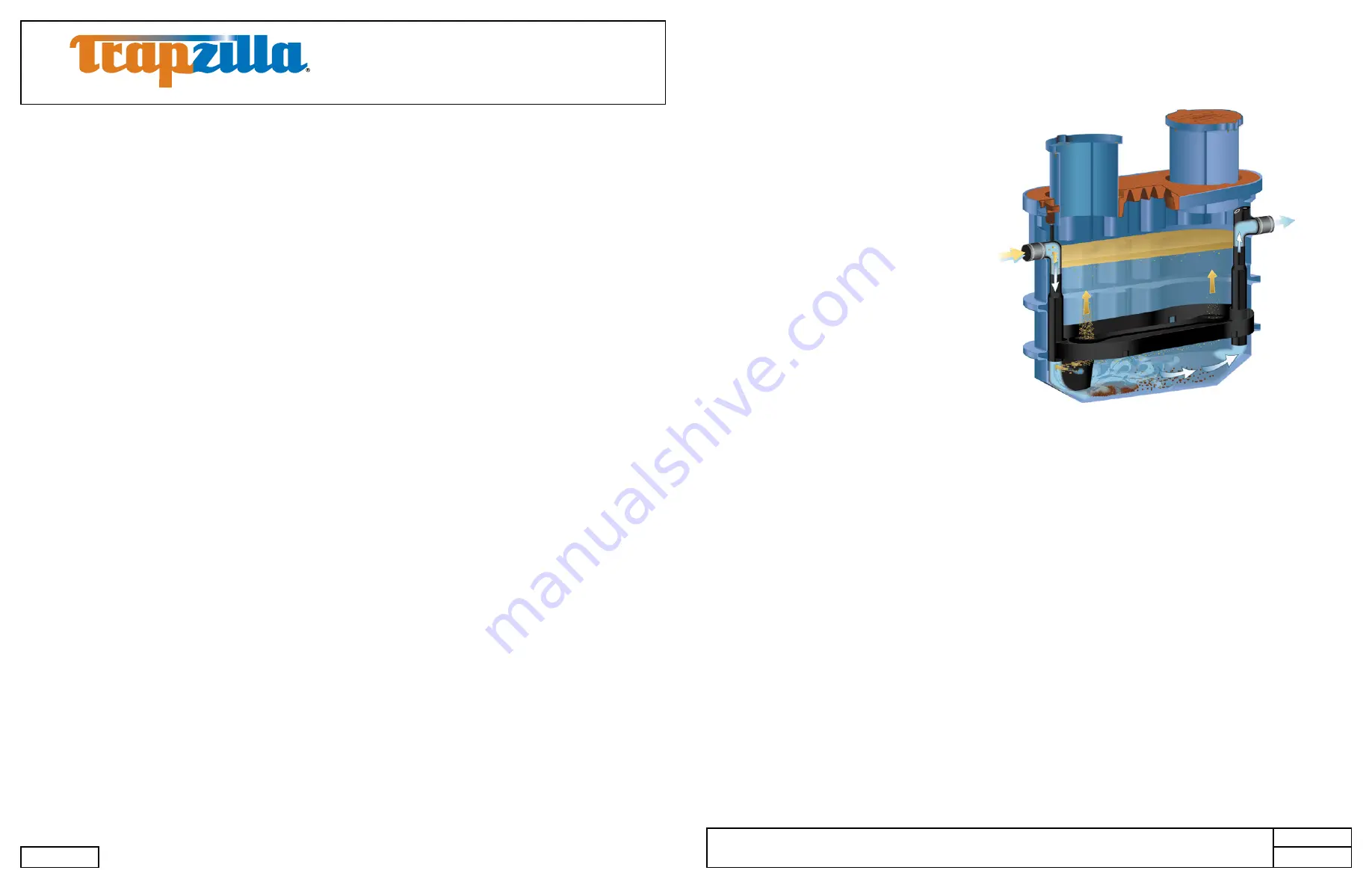
Grease Interceptor collects free-floating
grease & oils contained in kitchen drain water
flows. As most food service facility managers
already know, grease buildup inside a
building’s grease containment system is a
major cause of problems due to exterior drain
line blockages. These problems jeopardize
normal operations as well as create health
and safety hazards within the facility itself.
The proper installation of a Trapzilla®
Supercapacity Grease Interceptor can
reduce or eliminate grease problems and
costly sewer surcharges and fines through
efficient separation and retention of free-
floating grease & oils.
The Trapzilla offers patented flat separation
curve technology. This means that the unit does not lose grease separation efficiency as it fills with
retained grease. Thus, the Trapzilla stores large quantities of grease without losing efficiency. The
unique compact design of the Trapzilla allows for installation into most facilities. Options are available
that enable a Trapzilla unit to be installed on the floor, suspended from the ceiling or in-ground outside
the facility.
Trapzilla units are designed to treat high flows of kitchen drainwater with large grease storage capacity
within a small footprint unit. These units are easy to maneuver into position and just as easy to plumb.
Hydromechanical grease interceptors, automatic recovery units, grease removal devices and other
similar plumbing devices receiving kitchen flows from sinks, floor drains, woks and other food bearing
sources may generate odors. There are many factors influencing odor evolution and dissemination.
These include room ventilation, kitchen menu, ambient temperatures, ware washing practices, grease/oil
input, daily input fluid volume, sanitizers, installation plumbing design and product maintenance/upkeep.
Odors are usually prevented by good area ventilation, frequent fluid inputs, good product maintenance
practices and proper product installation. Additional steps, including aeration, chlorination, pH control,
improved area ventilation and additional maintenance may be needed at some sites.
*Devices formerly referred to as grease traps are now called hydromechanical grease interceptors.
Contents
1. System Overview.................................................................................................................................... 3
2. Models and Options................................................................................................................................ 4
2.1 Models ........................................................................................................................................... 4
2.2 Options .......................................................................................................................................... 5
3. Plumbing Installation .............................................................................................................................. 6
3.1 Plumbing Considerations Prior to Installation ................................................................................ 6
3.1.1 Locating the Unit ................................................................................................................... 6
3.1.2 Inlet/Outlet Piping ................................................................................................................. 6
3.1.3 Flow Controls ........................................................................................................................ 6
3.1.4 Venting the Outlet ................................................................................................................. 6
3.1.5 High Head Height Applications Over Six (6) Feet (1.95 m) .................................................. 6
3.2 Vessel Vent Connection .................................................................................................................. 7
3.3 Plumbing Configurations ................................................................................................................ 8
3.3.1
One
TZ-1826 ......................................................................................................................... 8
3.3.2 Installing Multiple Trapzilla Units in Parallel ........................................................................... 9
3.3.3 Installing Multiple Trapzilla Units in Series ............................................................................. 10
4. Above-Ground Installation ...................................................................................................................... 11
4.1 Components for Above-Ground Installations .................................................................................. 11
4.2 Instructions for Assembling and Attaching External Brace ............................................................. 12
4.3 Instructions for Installing Multiple Trapzilla Units Above-Ground .................................................... 12
4.3.1 Installing TZ-1826-SSA with TSS-95-SSA in Series .............................................................. 12
4.3.2 Construction of Riser for TSS-95-SSA installation in series with TZ-1826-SSA .................... 13
4.3.3 Installing Multiple TZ-1826-SSA in Series ............................................................................. 13
4.3.4 Installation of Pipe Hangers with Above-Ground Units .......................................................... 14
5. In-Ground Installation Instructions .......................................................................................................... 15
5.1 Single TZ-1826 Installed In-Ground ............................................................................................... 15
5.2 TZ-1826 with Optional ECA-TZ-29 Extension Collars .................................................................... 16
5.3 Concrete Specifications for In-Ground Installation ......................................................................... 17
5.4 Concrete Calculations for TZ-1826 Models/Components* ............................................................. 17
5.5 Trimming and Setting the ECA-TZ-18 Single-Piece Extension Collar ............................................ 18
6. Unit Maintenance.................................................................................................................................... 20
6.1 Measuring Grease/Solids Levels .................................................................................................... 20
6.2 Pumping/Servicing Unit .................................................................................................................. 21
7. Limited Warranty and Remedy ............................................................................................................... 22


