


Hardware Manual COMBILOG 1020
105
11.4 Output Format
The data format can be user defined by means of configuration
software
COMBILOG.EXE
. The datalogger adjusts the data for-
mats accordingly and makes sure that the data are available in
the selected unit.
For transmission in ASCII- and PROFIBUS-format, the format
settings listed in table 11.2 and 11.3 can be chosen. By transmis-
sion in MODBUS-format the output format (integer or real) is rec-
ognised automatically (table 11.4). The Coding of a real value in
MODBUS- and PROFIBUS-format is as follows:
Coding of the real value:
x = s ee...ee mmm.....mmm
Value:
( )
,
−
⋅
⋅
−
1
2
1
127
S
e
m
# : <1> <- 8 -> <----- 23 ---->
Value (0 < e < 255):
(-1)
S
*2
e-127
*1,m
Value (e=0):
(-1)
S
*2
e-126
*0,m
format settings
range of values
unit
dependent on sensor
field length
1 . . . . . . . . . . . . . . . . . . 8
decimals
0 . . . field length-1 (max. 6)
Table 11.2 Format settings for transmission in ASCII-format
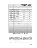
format settings
length
range of values
b o o l
1 byte
(dec 0: FALSE) and (dez 255: TRUE)
integer 2
byte
(dec - 32768)
≤
i
≤
(dec +32767)
r e a l
4 byte
(dec - 2
129
)
≤
x
≤
(dec + 2
129
)
SET 8
1 byte
(dec 0)
≤
i
≤
(dec 255
)
Table 11.3 Format settings for transmission in PROFIBUS-format
Summary of Contents for COMBILOG 1020
Page 1: ...COMBILOG 1020 Datalogger Hardware Manual Version 3 09...
Page 2: ...Hardware Manual COMBILOG 1020 2 Issue 03 11 2005 Technical data are subject to change...
Page 4: ...Hardware Manual COMBILOG 1020 4...
Page 6: ...Hardware Manual COMBILOG 1020 6...
Page 12: ...Hardware Manual COMBILOG 1020 12...
Page 86: ...Hardware Manual COMBILOG 1020 86 Bild 8 1 Example Master Slave System...
Page 169: ...Hardware Manual COMBILOG 1020 169...
Page 170: ...Hardware Manual COMBILOG 1020 170...