


Hardware Manual COMBILOG 1020
139
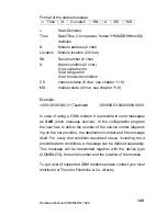
x ... “ M“ : Monitor program
x ... “ U“ : Universal program
x ... “ T“ : Calibration and test program
x ... “ S“ : Application specific program
x ... “ R“ : MODBUS-RTU-Program
xy.yy : Version
Status information
Register
Type Contents
Length
0500
ro
Module status
2 Byte
0501..0502
ro
Channel status
4 Byte
<Module status>:
M16..M13 , M12..M9 = hex xy = 1. Byte
M8..M5 , M4..M1
= hex xy = 2. Byte
If the bit Mn in the module status is set it indicates that an error
has occurred in the sensor module, the following applies:
M1 = 1: EEPROM - Error
M2 = 1: Flash - Error
M3 = 1: ADC - Error
M4 = 1: Configuration - Error
M5 = 1: No memory card
M6 = 1: RTC - Error
M7...M16 Are currently not occupied
<Channel status>: K32..K29 , K28..K25 = hex xy = 1. Byte
K24..K21 , K20..K17 = hex xy = 2. Byte
K16..K13 , K12..K9 = hex xy = 3. Byte
K8..K5 ,
K4..K1
= hex xy = 4. Byte
If the bit Kn in the channel status is set it indicates that an error
has occurred in channel n.
Summary of Contents for COMBILOG 1020
Page 1: ...COMBILOG 1020 Datalogger Hardware Manual Version 3 09...
Page 2: ...Hardware Manual COMBILOG 1020 2 Issue 03 11 2005 Technical data are subject to change...
Page 4: ...Hardware Manual COMBILOG 1020 4...
Page 6: ...Hardware Manual COMBILOG 1020 6...
Page 12: ...Hardware Manual COMBILOG 1020 12...
Page 86: ...Hardware Manual COMBILOG 1020 86 Bild 8 1 Example Master Slave System...
Page 169: ...Hardware Manual COMBILOG 1020 169...
Page 170: ...Hardware Manual COMBILOG 1020 170...