


Hardware Manual COMBILOG 1020
29
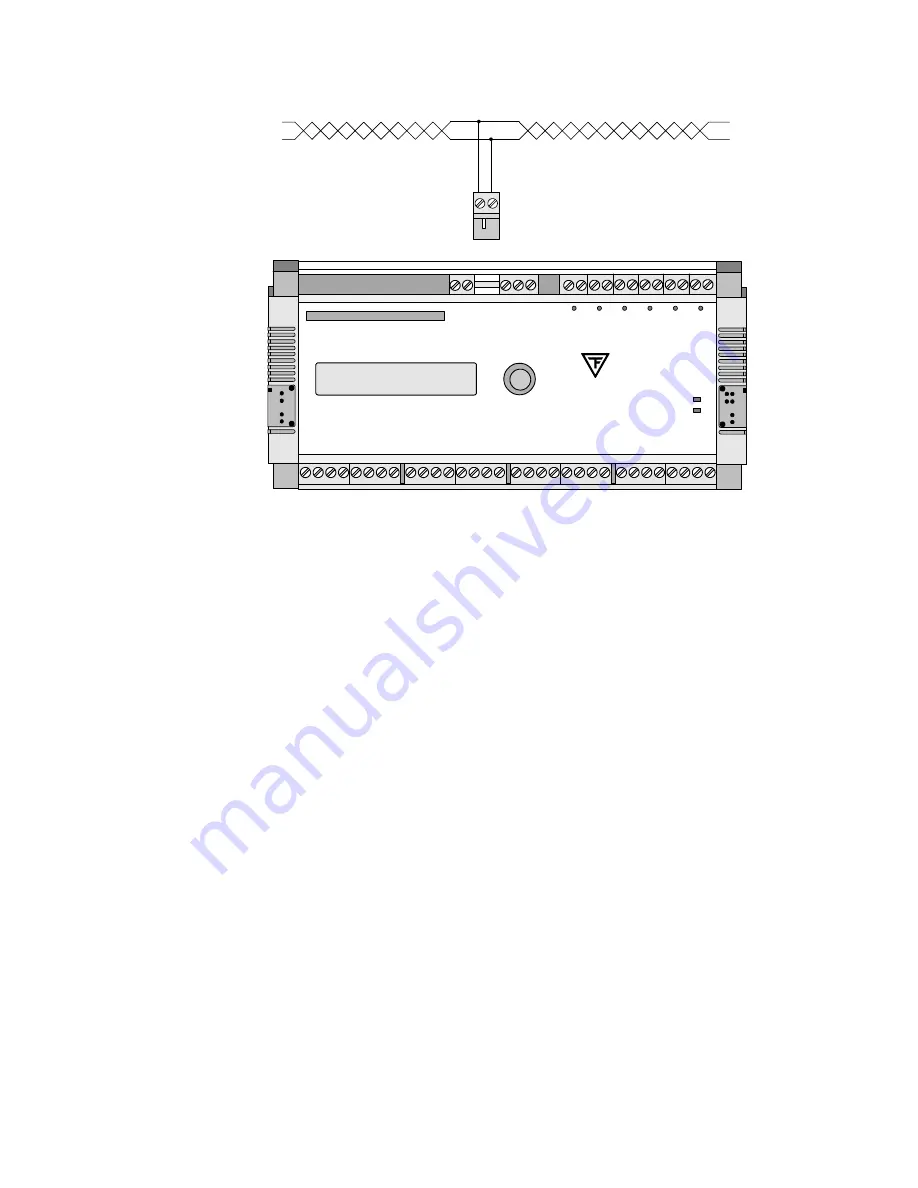
RS-485 Busverbindung
A
B
A'
B'
ERR
RUN
TH. FRIEDRICHS & CO.
COMBILOG 1020
D I G I T A L
A I N 8
A I N 7
A I N 6
A I N 5
A I N 4
A I N 3
A I N 2
A I N 1
A N A L O G
S
O
U
R
C
E
SELECT
In
+
In
-
A
G
N
D
S
O
U
R
C
E
In
+
In
-
A
G
N
D
S
O
U
R
C
E
In
+
In
-
A
G
N
D
S
O
U
R
C
E
In
+
In
-
A
G
N
D
S
O
U
R
C
E
In
+
In
-
A
G
N
D
S
O
U
R
C
E
In
+
In
-
A
G
N
D
S
O
U
R
C
E
In
+
In
-
A
G
N
D
S
O
U
R
C
E
In
+
In
-
A
G
N
D
MEMORY CARD / PCMCIA
Display
2 x 16 Character
C
O
M
T
X
R
X
B
A
0
V
+
1
0.
.1
8V
SUPPLY
RS 485
RS 232
I/O
1
0
V
I/O
2
0
V
I/O
3
I/O
4
I/O
5
0
V
I/O
6
0
V
0.1 AM
0
V
0
V
Figure 3.4 Connection of the datalogger to the bus by a stub cable
3.8 Sensor
Connection
The analog and digital signal inputs and outputs are wired ac-
cording to measurement task, to the transducer (sensor) that is
used, and to the number of connected sensors. The pinout arran-
gements for the various types of measurement are described in
chapter 5. The respectively valid pin assignment is determined by
means of the configuration software.
Since the digital outputs are "passive" the processing of external
elements always requires an external current supply. In case of
larger loads this should be independent of the datalogger supply.
RS-485 bus connection
Summary of Contents for COMBILOG 1020
Page 1: ...COMBILOG 1020 Datalogger Hardware Manual Version 3 09...
Page 2: ...Hardware Manual COMBILOG 1020 2 Issue 03 11 2005 Technical data are subject to change...
Page 4: ...Hardware Manual COMBILOG 1020 4...
Page 6: ...Hardware Manual COMBILOG 1020 6...
Page 12: ...Hardware Manual COMBILOG 1020 12...
Page 86: ...Hardware Manual COMBILOG 1020 86 Bild 8 1 Example Master Slave System...
Page 169: ...Hardware Manual COMBILOG 1020 169...
Page 170: ...Hardware Manual COMBILOG 1020 170...


