background image

� 

CESSNA 

MODEL 172R (180 HP) 

SECTION 6 

WEIGHT & BALANCE/ EQUIPMENT LIST 

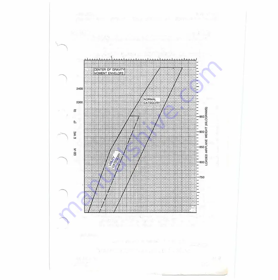
LOAOEO AJAPLANE MOMENT/1000 (KILOGRAM· MILLIMETEAS) 

600 

700 

8 0 

900 

1000 

1100 

1200 

1300 

1400 

1500 

2600 

2500 

�2200 

... 

l: 

£12100 

�2000 

er 

�1900 

1800 

1700 

1600 

.Lt 

1500 

50 

Nov 24/99 

1100 

1050 

1000 

700 

•• 

-650 

·!·•! 

-

t"

-

60 

70 

80 

90 

100 

110 

120 

130 

LOAOEO AIAPLANE  MO�NTIIOOO  (POUND • INCHES) 

058SC1007 

Figure  6-7.  Center 

of 

Gravity  Moment  Envelope 

6-15

Summary of Contents for 172R180HP

Page 1: ...72 72 01 Serial No l728 0 6 24 Registration No N4 8OER This publication includes the material required to be furnished to the pilot by FAR Part 23 and consttutes the FAA Approved Airplane Flight Manua...

Page 2: ...L WAS PROVIDED FOR THE AIRPLANE IDENTIRED ON THE TITLE PAGE ON jr 0 _______ SUBSEQUENT REVISIONS SUPPLIED BY THE CESSNA AIRCRAFT COMPANY MUST BE PROPERLY INSERTED 8 The Cessna Aircraft Company Aircraf...

Page 3: ...REVISION MODEL 172R180HP PILOT S OPERATING HANDBOOK AND FAA APPROVED AIRPLANE FLIGHT MANUAL REVISION 2 4 OCTOBER 2001 172R180PHUSR02 INSERT THE FOLLOWING PAGES INTO THE PILOT S OPERATING HANDBOOK j...

Page 4: ...I I I _ I l...

Page 5: ...ER MODEL 172R 180 HP Oct 4 01 Pilot s Operating Handbook and FAA Approved Airplane Flight Manual Serial Numbers 172R80001 and On Original Issue 24 November 1999 Revision 2 4 October 2001 PART NUMBER 1...

Page 6: ......

Page 7: ...0 RPM PROPELLER Fixed Pitch Diameter 76 IN I The above performance figures are based on airplane weights at 2550 pounds standard atmospheric conditions level hard surfaced dry runways and no wind They...

Page 8: ...nts are individual documents and may be issued or revised without regard to revision dates which apply to the POH Iitself These supplements contain their own Log of Effective Pages which should be use...

Page 9: ...r each page within the POH At original issue all pages will contain the same date As revisions to the POH occur these dates will change on effected pages When two pages display the same page number th...

Page 10: ...n that requires extensive revision revision bars will appear the full length of text New art added to an existing section will be identified by a single pointing hand indicator adjacent to the figure...

Page 11: ...ov24 99 1 1 Oct4 01 1 2 Nov24 99 1 3 Oct4 01 1 4 Oct4101 1 5 Oct 4 01 1 6 Nov24 99 1 7 Oct4 01 1 8 Nov24 99 1 9 Nov24 99 1 10 Nov24 99 1 11 Nov24 99 1 12 Nov24 99 1 13 Oct4 01 1 14 Nov24 99 1 15 Nov24...

Page 12: ...01 Nov 24 99 Oct 4 01 Oct 4 01 Oct 4 01 Oct 4 01 Oct 4 01 Nov 24 99 Oct 4 01 Nov 24 99 Nov 24 99 Oct 4 01 Oct 4 01 Nov 24 99 Nov 24 99 Nov 24 99 PAGE 5 2 Blank 5 3 5 4 5 5 5 6 5 7 5 8 5 9 5 10 5 11 5...

Page 13: ...24 99 Oct 4 01 Oct 4 01 Oct 4 01 Oct 4 01 Oct 4 01 Oct 4 01 Oct 4 01 Oct 4 01 Nov 24 99 Oct 4 01 Oct 4 01 Oct 4 01 Oct 4 01 Oct 4 01 Oct 4 01 Oct 4 01 PAGE 7 34 7 35 7 36 7 37 7 38 7 39 7 40 7 41 7 4...

Page 14: ...OF EFFECTIVE PAGES CESSNA MODEL 172R 180 HP LOG OF EFFECTIVE PAGES Continued PAGE DATE 8 20 Oct 4 01 8 21 Oct 4 01 8 22 Oct 4 01 8 23 Oct 4 01 8 24 Oct 4 01 9 1 Oct 4 01 9 2 Blank Nov 24 99 xii Oct 4...

Page 15: ...t GENERAL...

Page 16: ...1 J a w z w c...

Page 17: ...ions and Terminology General Airspeed Terminology And Symbols Meteorological Terminology Engine Power Terminology Airplane Performance And Flight Planning Terminology Weight And Balance Terminology Me...

Page 18: ...SECTION 1 GENERAL CESSNA MODEL 172R 180 HP 1 2 I 36 1 r 76 MAX os o 05101 Figure 1 1 Three View Normal Ground Attitude Sheet 1 of 2 Nov 24 99...

Page 19: ...NOTE 3 PROPELLER GROUND CLEARANCE IS 11 1 4 NOTE 4 WING AREA IS 174 SQUARE FEET NOTE 5 MINIMUM TURNING RADIUS PIVOT POINT TO OUTBOARD WING TIP IS 27 5 1 2 NOTE 6 NORMAL GROUND ATTITUDE IS SHOWN WITH...

Page 20: ...urer Textron Lycoming Engine Model Number IO 360 L2A Engine Type Normally aspirated direct drive air cooled horizontally opposed fuel injected four cylinder engine with 360 cu in displacement Horsepow...

Page 21: ...n the Left or Right position Refer to Figure 1 1 for normal ground attitude dimensions I Oil Specification MIL L 6082 or SAE J1966 Aviation Grade Straight Mineral Oil I Used when the airplane was deli...

Page 22: ...0 F 30 30 40 or 20W 40 Below 12 c 10 F 20 30 or 20W 30 1a0 c 0 F to 32 c 90 F 20W 50 20W 50 or 1SW 50 All Temperatures 1SW 50 or 20W 50 NOTE When operating temperatures overlap use the lighter grade o...

Page 23: ...rear seat must not be occupied and the baggage compartment must be empty STANDARD AIRPLANE WEIGHTS Standard Empty Weight Maximum Useful Load Normal Category Maximum Useful Load Utility Category CABIN...

Page 24: ...ture VA Maneuvering Speed is the maximum speed at which full or abrupt control movements may be used without overstressing the airframe VFE Maximum Flap Extended Speed is the highest speed permissible...

Page 25: ...It may be expressed in either degrees Celsius or degrees Fahrenheit Standard Temperature is 15 C at sea level pressure altitude and decreases by 2 c for each 1000 feet of altitude Pressure Altitude i...

Page 26: ...The value shown is not considered to be limiting Usable Fuel is the fuel available for flight planning Unusable Fuel is the quantity of fuel that can not be safely used in flight Gallons Per Hour is t...

Page 27: ...ch an airplane or equipment would balance if suspended Its distance from the reference datum is found by dividing the total moment by the total weight of the airplane Center of Gravity Arm is the arm...

Page 28: ...of fuel used for start taxi and runup Maximum Takeoff Weight is the maximum weight approved for the start of the takeoff roll Maximum Landing Weight is the maximum weight approved for the landing tou...

Page 29: ...convert U S measurement supplied with the Pilot s Operating Handbook into metric and imperial measurements The standard followed for measurement units shown is the National Institute of Standards Tech...

Page 30: ...60 202 83 205 03 207 24 209 44 211 64 224 87 227 08 229 28 231 49 233 69 POUNDS INTO KILOGRAMS LIVRES EN KILOGRAMMES 2 3 4 5 6 kg kg kg kg kg 0 907 1 361 1 814 2 268 2 722 5 443 5 897 6 350 6 804 7 25...

Page 31: ...ounds x 454 Kilograms POUNDS KILOGRAMS 220 100 210 95 200 90 190 85 180 80 170 75 160 150 70 140 65 130 60 120 55 110 50 100 45 90 40 80 35 70 30 60 25 50 40 20 30 15 20 10 10 5 0 0 Units x 10 100 etc...

Page 32: ...6 180 45 183 73 206 69 209 97 213 25 216 53 239 50 242 78 246 06 249 34 272 31 275 59 278 87 282 15 305 12 308 40 311 68 314 96 337 93 341 21 344 49 347 77 FEET INTO METERS PIEDS EN METRES 3 4 5 6 m m...

Page 33: ...ET 320 300 280 260 240 220 200 180 160 140 120 100 80 60 40 20 0 SECTION 1 GENERAL Feet x 305 Meters METERS 100 95 90 85 80 75 70 65 60 55 50 45 40 35 30 25 20 15 10 5 0 Units x 10 100 etc Figure 1 3...

Page 34: ...40 29 134 29 528 29 921 30 315 32 283 32 677 33 071 33 465 33 858 34 252 36 220 36 614 37 008 37 402 37 795 38 189 40 157 40 551 40 945 41 339 41 732 42 126 INCHES INTO CENTIMETERS POUCES EN CENTIMETR...

Page 35: ...imeters x 394 Inches Inches x 2 54 Centimeters Nov 24 99 INCHES CENTIMETERS 10 25 24 9 23 22 21 8 7 20 19 18 17 16 5 15 5 14 13 12 11 4 __ 10 3 9 8 7 6 2 5 4 1 3 2 1 11 0 Units x 10 100 etc 0585T1028...

Page 36: ...Kilometers x 54 Nautical Miles STATUTE NAUTICAL MILES MILES KILOMETERS 115 100 100 110 95 95 180 105 90 90 170 100 85 85 160 95 150 90 80 80 85 75 75 140 80 70 70 130 75 65 65 120 70 60 60 110 65 55 5...

Page 37: ...0 238 20 458 20 678 20 898 21 118 22 438 22 658 22 878 23 098 23 318 7 IG 1 540 3 740 5 939 8 139 10 339 12 539 14 738 16 938 19 138 21 338 23 537 IMPERIAL GALLONS INTO LITERS GALLONS IMPERIAL EN LITR...

Page 38: ...rs x 22 Imperial Gallons 100 IMPERIAL 95 440 LITERS GALLONS 420 90 400 85 380 80 360 75 340 70 320 65 300 60 280 55 260 240 50 220 45 200 40 180 35 160 30 140 25 120 20 100 80 15 60 10 40 5 20 0 0 Uni...

Page 39: ...NS 100 U S 120 GALLONS 1OO LITERS 95 115 95 360 90 110 90 340 85 105 100 85 320 80 95 80 300 75 90 75 280 70 85 70 260 65 80 65 75 240 60 70 60 220 55 65 55 200 50 60 50 180 45 55 45 50 160 40 40 45 1...

Page 40: ...20 30 180 10 0 200 10 220 20 30 240 40 50 260 60 70 280 80 90 300 100 320 110 120 340 130 140 0 360 150 160 380 170 180 400 190 420 200 210 100 820 220 840 230 110 860 460 880 120 900 480 130 920 500...

Page 41: ...ITERS KILOGRAMS 100 100 95 150 135 95 130 90 140 125 90 85 120 85 130 AVGAS FUEL 115 80 110 80 75 120 105 75 70 110 100 70 95 65 100 90 65 60 85 60 90 80 55 75 55 50 80 70 50 45 70 65 45 60 40 60 55 4...

Page 42: ...SECTION 1 GENERAL AV GAS SPECIFIC GRAVITY 0 72 1 26 CESSNA MODEL 172R 180 HP Figure 1 9 Quick Conversions Nov 24 99...

Page 43: ...2 r 3 0 z...

Page 44: ...2 v z 0 i e i...

Page 45: ...ight Limits 2 7 Normal Category 2 7 Utility Category 2 7 Center Of Gravity Limits 2 7 Normal Category 2 7 Utility Category 2 8 Maneuver Limits 2 8 Normal Category 2 8 Utility Category 2 9 Flight Load...

Page 46: ...l...

Page 47: ...ptions NOTE the Supplements Section 9 of this Pilot s Handbook for amended operating limitations procedures performance data and other information for airplanes equipped with specific NOTE The airspee...

Page 48: ...Do not exceed this speed in any operation VNo Maximum Structural 126 129 Do not exceed this Cruising Speed speed except in smooth air and then only with caution VA Maneuvering Speed Do not make full...

Page 49: ...ght Vs at most forward C G with flaps retracted Upper limit is maximum structural cruising speed Yellow Arc 129 163 Operations must be conducted with caution and only in smooth air Red Line 163 Maximu...

Page 50: ...el Number 1A170E JHA7660 Propeller Diameter Maximum 76 inches Minimum 75 inch minimum POWERPLANT INSTRUMENT MARKINGS Powerplant instrument markings and their color code significance are shown in Figur...

Page 51: ...is 120 lbs UTILITY CATEGORY Maximum Ramp Weight 2208 lbs Maximum Takeoff Weight 2200 lbs Maximum Landing Weight 2200 lbs Maximum Weight in Baggage Compartment In the utility category the baggage comp...

Page 52: ...s airplane is certificated in both the normal and utility category The normal category is applicable to aircraft intended for non aerobatic operations These include any maneuvers incidental to normal...

Page 53: ...MMENDED ENTRY SPEEO Chandelles 105 Knots Lazy Eights 105 Knots Steep Turns 95 Knots Spins Slow Deceleration Stalls Except Whip Stalls Slow Deceleration Abrupt use of the controls is prohibited above 9...

Page 54: ...aps Up 4 4g 1 76g Flaps Down 3 0g The design load factors are 150 of the above and in all cases the structure meets or exceeds design loads KINDS OF OPERATION LIMITS The airplane is equipped for day V...

Page 55: ...e definition ADDITIONAL FUEL LIMITATIONS Takeoff and land with the fuel selector valve handle in the BOTH position Maximum slip or skid duration with one tank dry 30 seconds Operation on either LEFT o...

Page 56: ...h must be complied with when operating this airplane in this category or in the Utility Category are contained in the Pilot s Operating Handbook and FAA Approved Airplane Flight Manual Normal Category...

Page 57: ...cap FUEL ALL FLIGHT ATTITUDES RIGHT 26 5 GAL LEVEL FLIGHT ONLY 100LU100 MIN GRADE AVIATION GASOLINE CAP 26 5 U S GAL USABLE CAP 17 5 U S GAL USABLE TO BOTTOM OF FILLER INDICATOR TAB 4 On flap control...

Page 58: ...S COMBINED FOR ADDITIONAL LOADING INSTRUCTIONS SEE WEIGH T ANDBALANCE DATA 6 A calibration card must be provided to indicate the accuracy of the magnetic compass in 30 increments 7 On the oil fiiler c...

Page 59: ...PARTITION MUST BE SERVICED IN ACCORDANCE WITH FAR PART 91 207 11 On forward face of firewall adjacent to the battery CAUTION 24 VOLTS D C THIS AIRCRAFT IS EQUIPPED WITH ALTERNATOR AND A NEGATIVE GROU...

Page 60: ...i c t...

Page 61: ......

Page 62: ......

Page 63: ...diately After Takeoff Engine Failure During Flight Restart Procedures Forced Landings Emergency Landing Without Engine Power Precautionary Landing With Engine Power Ditching Fires During Start On Grou...

Page 64: ...Fires Emergency Operation In Clouds Vacuum System Failure Executing A 180 Turn In Clouds Emergency Descent Through Clouds I Recovery From Spiral Dive In The Clouds Inadvertent Flight Into Icing Condi...

Page 65: ...untered However should an emergency arise the basic guidelines described in this section should be considered and applied as necessary to correct the problem Emergency procedures associated with stand...

Page 66: ...Ignition Switch OFF 6 Master Switch OFF ENGINE FAILURE IMMEDIATELY AFTER TAKEOFF 1 Airspeed 70 KIAS flaps UP 65 KIAS flaps DOWN 2 Mixture IDLE CUT OFF 3 Fuel Shutoff Valve OFF Pull Full Out 4 Ignition...

Page 67: ...ll Full Out 6 Ignition Switch OFF 7 Wing Flaps AS REQUIRED 30 recommended 8 Master Switch OFF when landing is assured 9 Doors UNLATCH PRIOR TO TOUCHDOWN 10 Touchdown SLIGHTLY TAIL LOW 11 Brakes APPLY...

Page 68: ...IN DESCENT AT 55 KIAS NOTE If no power is available approach at 70 KIAS with flaps up or at 65 KIAS with 10 flaps 7 Approach High Winds Heavy Seas INTO THE WIND Light Winds Heavy Swells PARALLEL TO SW...

Page 69: ...Switch OFF b Ignition Switch OFF 11 Parking Brake RELEASE 12 Airplane EVACUATE 13 Fire EXTINGUISH using fire extinguisher wool blanket or dirt 14 Fire Damage INSPECT repair damage or replace damaged c...

Page 70: ...power is necessary for continuance of flight to nearest suitable airport or landing area 7 Master Switch ON 8 Circuit Breakers CHECK for faulty circuit do not reset 9 Radio Switches OFF 10 Avionics M...

Page 71: ...blocking the air intake filter or in extremely rare instances ice completely blocking the fuel injection air reference tubes Change the throttle position to obtain maximum RPM This may require either...

Page 72: ...iate calibration tables in Section 5 LANDING WITH A FLAT MAIN TIRE 1 Approach NORMAL 2 Wing Flaps 30 3 Touchdown GOOD MAIN TIRE FIRST hold airplane off flat tire as long as possible with aileron contr...

Page 73: ...DURING FLIGHT Ammeter Indicates Discharge NOTE Illumination of VOLTS on the annunciator panel may occur during low RPM conditions with an electrical load on the system such as during a low RPM taxi Un...

Page 74: ...ssential Radio and Electrical Equipment OFF 9 Flight TERMINATE as soon as practical VACUUM SYSTEM FAILURE lleft Vacuum Annunciator L VAC or Right Vacuum Annunciator VAC R Illuminates AcAUTION IF VACUU...

Page 75: ...edge of procedures fresh ENGINE FAILURE If an engine failure occurs during the takeoff roll the most important thing to do is stop the airplane on the remaining runway Those extra items on the checkli...

Page 76: ...rt should be made to identify the cause of the failure If time permits an engine restart should be attempted as shown in the checklist If the engine cannot be restarted a forced landing without power...

Page 77: ...k 7700 Avoid a landing flare because of difficulty in judging height over a water surface The checklist assumes the availability of power to make a precautionary water landing If power is not availabl...

Page 78: ...t in elimination of the fire EMERGENCY OPERATION IN CLOUDS Total Vacuum System Failure If both the vacuum pumps fail in flight the directional indicator and attitude indicator will be disabled and the...

Page 79: ...s due to changing bank angles In addition keep hands off the control wheel and steer a straight course with rudder control by monitoring the tum coordinator Occasionally check the compass heading and...

Page 80: ...engine speed could be caused by ice blocking the air intake filter or in extremely rare instances ice completely blocking the fuel injection air reference tubes In either case the throttle should be...

Page 81: ...extend the recovery 6 AS ROTATION STOPS NEUTRALIZE RUDDER AND MAKE A SMOOTH RECOVERY FROM THE RESULTING DIVE NOTE If disorientation precludes a visual determination of the direction of rotation the sy...

Page 82: ...tings and enrichen the mixture to determine if continued operation on BOTH magnetos is practicable If not switch to the good magneto and proceed to the nearest airport for repairs ENGINE DRIVEN FUEL P...

Page 83: ...cessive rate of charge and insufficient rate of charge The following paragraphs describe the recommended remedy for each situation EXCESSIVE RATE OF CHARGE After engine starting and heavy electrical u...

Page 84: ...ill resume land the low voltage annunciator VOLTS will go off The avionics master switch may then be turned back on I If the annunciator illuminates again a malfunction is confirmed In this event the...

Page 85: ...4 oz 0 m J J 03 C i...

Page 86: ...I 4 w a 5 a w ou zO a a...

Page 87: ...7 Cabin 4 7 Empennage 4 8 Right Wing Trailing Edge 4 8 Right Wing 4 8 Nose 4 9 Left Wing 4 10 Left Wing Leading Edge 4 11 Left Wing Trailing Edge 4 11 Before Starting Engine 4 11 Starting Engine With...

Page 88: ...ES Preflight Inspection Starting Engine Taxiing Before Takeoff Warm Up Magneto Check Alternator Check Landing Lights Takeoff Power Check Wing Flap Settings Crosswind Takeoff Enroute Climb Cruise ILean...

Page 89: ...tinued Page Landing 4 31 Normal Landing 4 31 Short Field Landing 4 32 Crosswind Landing 4 32 Balked Landing 4 32 Cold Weather Operation 4 33 Starting 4 33 Winterization Kit 4 34 Hot Weather Operation...

Page 90: ......

Page 91: ...IAS Short Field Takeoff Flaps 10 Speed at 50 Feet 56 KIAS Enroute Climb Flaps Up Normal Sea Level 75 85 KIAS Normal 10 000 Feet 70 80 KIAS Best Rate of Climb Sea Level 74 KIAS Best Rate of Climb 10 00...

Page 92: ...access to the upper wing surfaces for visual checks and refueling operations In cold weather remove even small accumulations of frost ice or snow from wing tail and control surfaces Also make sure th...

Page 93: ...ROPELLER THROUGH BY HAND TREAT THE PROPELLER AS IF THE IGNITION SWITCH WERE ON DO NOT STAND NOR ALLOW ANYONE ELSE TO STAND WITHIN THE ARC OF THE PROPELLER SINCE A LOOSE OR BROKEN WIRE OR A COMPONENT M...

Page 94: ...s EXTEND 19 Pilot Heat ON Carefully check that pilot tube is warm to touch within 30 seconds 20 Pitot Heat OFF 21 Master Switch OFF I 22 Trim Control NEUTRAL 23 Baggage Door CHECK lock with key 24 Aut...

Page 95: ...VIDENCE OF CONTAMINATION STILL EXISTS THE AIRPLANE SHOULD NOT BE FLOWN TANKS SHOULD BE DRAINED AND SYSTEM PURGED BY QUALIFIED MAINTENANCE PERSONNEL ALL EVIDENCE OF CONTAMINATION MUST BE REMOVED BEFORE...

Page 96: ...LEFT WING 1 Fuel Quantity CHECK VISUALLY for desired level 2 Fuel Filler Cap SECURE and VENT UNOBSTRUCTED 3 Fuel Tank Sump Quick Drain Valves DRAIN at least a cupful of fuel using sampler cup from ea...

Page 97: ...ING Trailing Edge 1 Aileron CHECK for freedom of movement and security 2 Flap CHECK for security and condition BEFORE STARTING ENGINE 1 Preflight Inspection COMPLETE 2 Passenger Briefing COMPLETE 3 Se...

Page 98: ..._ c j Q Q If engine is warm omit priming__pr69edure of s e Ds 5 6 Cri d 7 above J 1 8 Ignition Switch START release when engine start A 9 Mixture ADVANCE smoothly to RICH when engine f1 es I 1V NOTE...

Page 99: ...rts 10 Mixture ADVANCE smoothly to RICH when engine fires NOTE If engine floods turn off auxiliary fuel pump place mixture in idle cut off open throttle 1 2 to full and crank engine When engine fires...

Page 100: ...tor Panel Ensure no annunciators are illuminated 12 Throttle CHECK IDLE 13 Throttle 1000 RPM or LESS 14 Throttle Friction Lock ADJUST 15 Strobe Lights AS DESIRED 16 Radios and Avionics SET 17 NAV GPS...

Page 101: ...AA Approved Temporary Revision page s may or may not be applicable to your serial airplane Please refer to the individual FAA Approved Temporary Revision page s to determine applicability status for y...

Page 102: ...tive Pages in the front of this basic U S Pilot s Operating Handbook and FAA Approved Airplane Flight Manual TEMPORARY PAGE REVISION NUMBER NUMBER 172PHTR01 4 12 172PHTR02 3 20 172R180PHUS 03 TR03 6 1...

Page 103: ...lnser1 this temporary revision in the Model 172R with 180HP Engine as Modified by MK172 72 01 basic Pilot s Operating Handbook and FAA Approved Airplane Flight Manual adjacent to page 4 14 This tempo...

Page 104: ...TEMPORARY REVISION FOR CESSNA PILOrs OPERATING HANDBOOK AND FAA APPROVED AIRPLANE FLIGHT MANUAL BEFORE TAKEOFF 12 Throttle Control CHECK IDLE 13 Throttle Control 1000 RPM or LESS 172R180PHUS 03 TR04...

Page 105: ...sert this temporary revision in the Model 172R with 180HP Engine as Modified by MK172 72 01 basic Pilot s Operating Handbook and FAA Appro ved Airplane Flight Manual adjacent to page 4 22 This tempora...

Page 106: ...le against the idle stop approximately 675 RPM and accelerates smoothly the engine is ready for takeoff Since the engine is closely cowled for efficient in flight engine cooling the airplane should be...

Page 107: ...bstacles are cleared I 8 Wing Flap RETRACT slowly after reaching 75 KIAS ENROUTE CLIMB 1 Airspeed 70 85 KIAS 2 Throttle FULL OPEN 3 Mixture RICH above 3000 feet LEAN to obtain maximum RPM 1 CRUISE l 1...

Page 108: ...elow 85 KIAS 3 Airspeed 60 70 KIAS flaps DOWN 4 Touchdown MAIN WHEELS FIRST 5 Landing Roll LOWER NOSE WHEEL GENTLY 6 Braking MINIMUM REQUIRED SHORT FIELD LANDING 1 Airspeed 65 75 KIAS flaps UP 2 Wing...

Page 109: ...e SET SECTION 4 NORMAL PROCEDURES 2 Avionics Master Switch Electrical Equipment Autopilot if installed OFF 3 Mixture IDLE CUT OFF pulled full out 4 Ignition Switch OFF 5 Master Switch OFF 6 Control Lo...

Page 110: ...ights damage to nose wheel as a result of exceeding tow limits and avionics antennas Outside storage for long periods may result in dust and dirt accumulation on the induction air filter obstructions...

Page 111: ...also be inspected for obstructions ice or water especially after exposure to cold wet weather STARTING ENGINE In cooler weather the engine compartment temperature drops off rapidly following engine s...

Page 112: ...weather stop the engine and investigate Lack of oil pressure can cause serious engine damage NOTE Additional details concerning cold weather starting and operation may be found under COLD WEATHER OPE...

Page 113: ...ECTION t Nov 24 99 NOTE Strong quartering tail winds require caution Avoid sudden bursts of the throttle and sharp braking when the airplane is in this situation Use the steerable nose wheel and rudde...

Page 114: ...either magneto or show greater than 50 RPM differential between magnetos If there is a doubt concerning operation of the ignition system RPM checks at higher engine speeds will usually confirm whethe...

Page 115: ...ide maximum RPM Full throttle run ups over loose gravel are especially harmful to propeller tips When takeoffs must be made over a gravel surface it is very important that the throttle be advanced slo...

Page 116: ...control wheel forces during the initial climb CROSSWIND TAKEOFF Takeoffs into strong crosswind conditions normally are performed with the minimum flap setting necessary for the field length to minimi...

Page 117: ...on the time and fuel needed to complete any flight The Cruise Performance Table Figure 4 3 illustrates the true airspeed and nautical miles per gallon during cruise for various altitudes and percent p...

Page 118: ...sh the peak EGT as a reference point enrichen the mixture by the desired increment based on Figure 4 4 EGT Table MIXTURE DESCRIPTION EXHAUST GAS TEMPERATURE RECOMMENDED LEAN 50 Rich of Peak EGT Pilot...

Page 119: ...bove 3000 feet The mixture may remain leaned maximum RPM at full throttle for practicing maneuvers such as stalls and slow flight 3 Lean the mixture for maximum RPM during all operations at any altitu...

Page 120: ...ure full rich set the throttle at 1800 RPM to 2000 RPM Maintain this power setting for 1 to 2 minutes or until smooth engine operation returns 2 Retard the throttle to idle to verify normal engine ope...

Page 121: ...oose equipment including the microphone and rear seat belts should be stowed or secured For a solo flight in which spins will be conducted the copilot s seat belt and shoulder harness should also be s...

Page 122: ...spiral For the purpose of training in spins and spin recoveries a 1 or 2 lturn spin is adequate and should be used Up to 2 turns the spin will progress to a fairly rapid rate of rotation and a steep a...

Page 123: ...ohibited since the high speeds which may occur during recovery are potentially damaging to the flap wing structure LANDING NORMAL LANDING Normal landing approaches can be made with power on or power o...

Page 124: ...tings greater than 20 are used in sideslips with full rudder deflection some elevator oscillation may be felt at normal approach speeds However this does not affect control of the airplane Although th...

Page 125: ...internal accumulations of ice or snow If snow or slush covers the takeoff surface allowance must be made for takeoff distances which will be increasingly extended as the snow or slush depth increases...

Page 126: ...ot start during the first few attempts or if engine firing diminishes in strength it is probable that the spark plugs have been frosted over Preheat must be used before another start is attempted Duri...

Page 127: ...oise on the public 1 Pilots operating airplanes under VFR over outdoor assemblies of persons recreational and park areas and other noise sensitive areas should make every effort to fly not less than 2...

Page 128: ......

Page 129: ...ll PERFORMANCE...

Page 130: ...5 w u z a 0 a Ao...

Page 131: ...mal Static Source 5 9 Airspeed Calibration Alternate Static Source 5 1 o Figure 5 2 Temperature Conversion Chart 5 11 Figure 5 3 Stall Speeds 5 12 Figure 5 4 Crosswind Components 5 13 Figure 5 5 Short...

Page 132: ......

Page 133: ...d air turbulence may account for variations of 10 or more in range and endurance Therefore it is important to utilize all available information to estimate the fuel required for the particular flight...

Page 134: ...ght altitude and temperature For example in this particular sample problem the takeoff distance information presented for a weight of 2550 pounds pressure altitude of 2000 feet and a temperature of 30...

Page 135: ...the cruise performance characteristics presented in Figure 5 8 the range profile chart presented in Figure 5 9 and the endurance profile chart presented in Figure 5 10 The relationship between power...

Page 136: ...ay be made as noted on the climb chart The approximate effect of a non standard temperature is to increase the time fuel and distance by 10 for each 10 C above standard temperature due to the lower ra...

Page 137: ...iles 3 2 Hours 107 Knots The fuel required for cruise is 3 2 hours X 8 9 gallons hour 28 5 Gallons A 45 minute reserve requires 45 60 X 8 9 gallons hour 6 7 Gallons The total estimated fuel required i...

Page 138: ...ws Ground roll 650 Feet Total distance to clear a 50 foot obstacle 1455 Feet A correction for the effect of wind may be made based on Note 2 of the landing chart using the same procedure as outlined f...

Page 139: ...l flight or maximum power descent FLAPS UP KIAS 50 60 70 80 90 100 110 120 130 140 150 160 KCAS 56 62 70 78 87 97 107 117 127 137 147 157 FLAPS 100 KIAS 40 50 60 70 80 90 100 110 KCAS 51 57 63 71 80 8...

Page 140: ...P KIA 50 60 70 80 90 100 110 120 130 140 150 160 KCAS 56 62 68 76 85 95 105 115 125 134 144 154 FLAPS 10 KIA 40 50 60 70 80 90 100 110 KCAS 51 55 60 68 n 86 96 105 FLAPS 30 KIAS 40 50 60 70 80 85 KCAS...

Page 141: ...72R 180 HP SECTION 5 PERFORMANCE 120 100 80 LU 60 c LU i 40 LU LU CJ 20 LU 0 20 40 40 Nov 24 99 TEMPERATURE CONVERSION CHART ji f r r i r 1 20 0 20 40 60 DEGREES CELSIUS Figure 5 2 Temperature Convers...

Page 142: ...48 53 52 57 57 63 68 75 10 42 so 45 54 so 59 59 71 30 40 48 43 52 48 57 57 68 MOST FORWARD CENTER OF GRAVITY ANGLE OF BANK FLAP oo 30 45 60 SETTING KIAS KCAS KIAS KCAS KIAS KCAS KIAS KCAS UP 48 53 52...

Page 143: ...PERFORMANCE WIND COMPONENTS NOTE Maximum demonstrated crosswind velocity is 15 knots not a limitation Oct 4 01 1 z w z 0 E 0 0 C zo 10 15 0 5 10 15 20 25 30 35 CROSSWIND COMPONENT KNOTS Figure 5 4 Cr...

Page 144: ...195 2035 1310 2240 1440 2480 1585 2755 1745 3075 1920 3440 2120 3880 1 Short field technique as specified in Sect on 4 30 c 40 c Grnd Total Grnd Total Roll FtTo Roll FtTo Ft Clear Ft Clear 50 Ft 50 Ft...

Page 145: ...t To Roll Ft To Ft Clear Ft Clear Ft Clear SO Ft 50 Ft 50 Ft Obst Obst Obst 860 1470 925 1570 995 1685 940 1605 1010 1720 1085 1845 1030 1760 1110 1890 1190 2030 1130 1930 1215 2080 1305 2230 1240 213...

Page 146: ...030 1765 1110 1900 1195 6000 1050 1800 1130 1940 1220 2090 1310 7000 1150 1985 1245 2145 1340 2305 1435 8000 1270 2195 1370 2375 1475 2555 1580 NOTES 1 Short field technique as specified in Section 4...

Page 147: ...T FT S L 2000 4000 6000 8000 10 000 12 000 NOTE CLIMB SPEED KIA 74 73 73 73 72 72 72 RATE OF CLIMB FPM 20 c 0 C 20 c 855 785 710 760 695 625 685 620 555 575 515 450 465 405 345 360 300 240 255 195 135...

Page 148: ...4 1 2 6 4000 73 600 6 J 5 8 5000 73 550 8 1 9 10 6000 73 505 10 2 2 13 7000 73 455 12 2 6 16 8000 72 410 14 3 0 19 9000 72 360 17 3 4 22 10 000 72 315 20 3 9 27 11 000 72 265 24 4 4 32 12 000 72 220...

Page 149: ...42 89 6 3 4000 2600 83 120 11 1 77 120 10 4 72 119 9 8 2550 79 118 10 6 73 117 9 9 68 117 9 4 2500 74 115 10 1 69 115 9 5 64 114 8 9 2400 65 110 9 1 61 109 8 5 57 107 8 1 2300 58 104 8 2 54 102 7 7 51...

Page 150: ...97 2200 46 94 6 8 43 92 6 5 41 90 10 000 2700 78 124 10 5 72 123 9 8 67 122 2650 73 122 10 0 68 120 9 4 63 119 2600 69 119 9 5 64 117 9 0 60 115 2500 62 113 8 7 57 111 8 2 54 109 2400 55 106 7 9 51 10...

Page 151: ...e At All Altitudes Standard Temperature Zero Wind 12 000 10 000 8 000 t i ti NOTE ll i 1 This chart allows for the fuel used for engine start taxi takeoff and climb and the distance during climb 2 Per...

Page 152: ...t All Altitudes Standard Temperature 10000 8000 t ffi i t tl Hri t itH H t tltt HH t ti 1 6000 1 H l H r H 1 H t 4 w Q 5 4000 t tt H l H H H 1 H H t t H l t t 2000 H t H t SL rr f 1 r A I 4 5 6 7 8 EN...

Page 153: ...705 1535 725 6000 680 1500 705 1540 730 1580 755 7000 705 1545 730 1585 760 1625 785 8000 735 1585 760 1630 790 1670 815 NOTES 1 Short field technique as specified in Section 4 Total Ft To Clear 50Ft...

Page 154: ......

Page 155: ...6...

Page 156: ...J WEIGHT BALANCE n EQUIPMENT LIST J...

Page 157: ...T BALANCE EQUIPMENT LIST SECTION 6 WEIGHT BALANCE EQUIPMENT LIST TABLE OF CONTENTS Page Introduction 6 3 Airplane Weighing Procedures 6 3 Weight And Balance 6 6 Baggage Tie Down 6 8 Comprehensive Equi...

Page 158: ......

Page 159: ...IS THE RESPONSIBILITY OF THE PILOT TO ENSURE THE AIRPLANE IS LOADED PROPERLY OPERATION OUTSIDE OF PRESCRIBED WEIGHT AND BALANCE LIMITATIONS COULD RESULT IN AN ACCIDENT AND SERIOUS OR FATAL INJURY AIRP...

Page 160: ...CE LOWER PORTION NOTE STA 0 0 IT IS THE RESPONSIBILITY MAC 25 90 5 _a_ a _ o OF THE PILOT TO ENSURE THAT THE AIRPLANE IS LOADED PROPERLY LEVEL AT UPPER DOOR SILL OR LEVELING SCREWS ON LEFT SIDE OF TAI...

Page 161: ...SSIST IN LOCATING CG WITH AIRPLANE WEIGHED ON LANDING GEAR LEVELING PROVISIONS LONGITUDINAL LEFT SIDE OF TAILCONE AT FS 108 00 142 00 AIRPLANE AS WEIGHED TABLE posmoN SCALE READING SCALE DRIFT TARE NE...

Page 162: ...e weight and C G can be determined 6 Basic Empty Weight may be determined by completing Figure 6 1 WEIGHT AND BALANCE The following information will enable you to operate your Cessna within the prescr...

Page 163: ...QUIPMENT AFFECTING WEIGHT AND BALANCE AIRPLANE MODEL lsERIAL No IPAGE NUMBER WEIGHT CHANGE RUNNING ITEM NO BASIC EMPT Y DESCRIPTION ADDED REMOVED WEIGHT DATE OF ARTICLE OR OUT MODIFICATION WT ARM MOME...

Page 164: ...net having tie down straps is provided as standard equipment to secure baggage on the cabin floor aft of the rear seat baggage area 1 and in the aft baggage area baggage area 2 Six eyebolts serve as a...

Page 165: ...asured to the center of the areas shown NOTES 1 The usable fuel C G arm for integral tanks is located at station 48 0 Nov24 99 2 The rear cabin wall approximate station 108 or aft baggage wall approxi...

Page 166: ...MEASUREMENTS FIREWALL TIE DOWN RINGS 6 6 10 ___ __ I D 34 AFT BAGGAGE AREA DOOR OPENING DIMENSIONS WIDTH WIDTH HEIGHT HEIGHl TOP BOTTOM FRONT REAR CABIN DOORS 321 i 37 401 2 39 BAGGAGE DOOR 151 4 151...

Page 167: ...T CABIN WIDTH MEASUREMENTS INSTRUMENT PANEL REAR DOORPOST BULKHEAD I I I I I I o 1 b 2h 3b 4 o sb 60 I 10 so so 100 11o 120 1so 140 CABIN STATIONS C G ARMS 65 3 LWR WINDOW LINE CABIN FLOOR 0585X1023 F...

Page 168: ...Front Passenger Station 34 to 46 340 12 6 4 RearPassengers 340 24 8 5 Baggage Area 1 Station 82 to 108 120 Lbs Max I 56 4 6 6 Baggage Area 2 Station 108 to 142 50 Lbs Max 7 RAMP WEIGHT AND MOMENT add...

Page 169: ...nying attached FAA Approved Temporary Revision page s may or may not be applicable to your serial airplane Please refer to the individual FAA Approved Temporary Revision page s to determine applicabil...

Page 170: ...he removal instructions have been complied with Insert this page opposite the Log of Effective Pages in the front of this basic U S Pilot s Operating Handbook and FAA Approved Airplane Flight Manual T...

Page 171: ...Insert this temporary revision in the Model 172R with 180HP Engine as Modified by MK172 72 01 basic Pilot s Operating Handbook and FAA Approved Airplane Flight Manual adjacent to page 6 14 Removal Ins...

Page 172: ...TEMPORARY REVISION FOR CESSNA PILOT S OPERATING HANDBOOK AND FAA APPROVED AIRPLANE FLIGHT MANUAL This Page Intentionally Left Blank 172R180PHUS 03 TR03...

Page 173: ...IGHT MANUAL CENTER OF GRAVITY MOMENT ENVELOPE Loaded Airplane MomenV1000 Kilogram Millimeters 600 700 800 900 1000 1100 1200 1300 1400 1500 2600t r r __ _ _ _ ___ 1150 1600 700 1500 50 60 70 80 90 100...

Page 174: ...imeters Aft of Datum FS 0 0 875 925 975 1025 1075 1125 1175 1225 900 950 I 1000 1050 1100 1150 1200 1150 2400 1100 2300 1050 1 2200 1000 U E t2100 950 0 cij 1 2000 900 t cij 0 1900 I O 850 iii e 1800...

Page 175: ...ins lbs 1000 Weight Moment Lb ins lbs 1000 Weight Moment Lb ins lbs 1000 NOTE When several loading configurations are representative of your operations it may be useful to fill out one or more of the...

Page 176: ...300 t C iii 250 f Lg I 150 l a l 1 e _ j 75 i j_ i_r _ r 50 I J I NOTE LINE REPRESENTING ADJUSTABLE SEATS SHOWS THE PILOT OR PASSENGER CENTER OF GRAVITY ON ADJUSTABLE SEATS POSITIONED FOR AN AVERAGE...

Page 177: ...LOGRAM MILLIMETEAS 600 700 8 0 900 1000 1100 1200 1300 1400 1500 2600 2500 0 2200 0 l 12100 2000 er 1900 g 1800 1700 1600 Lt 1500 50 Nov 24 99 1100 1050 1000 700 650 t 60 70 80 90 100 110 120 130 LOAO...

Page 178: ...1I 111I Iti 11111 I 11111 I 11111111I11111111 I 11 II I I 111 1 _ M t t f 1050 1000 2200 50 0 e l f t l 1 i t f t t _ a 2100 _UTILITY ORMAL 900 w T CATEGORY __ ATEGORv 2000 ___ _ a 1 1900 n 7 1 _ 1 _...

Page 179: ...s or equipment for FAA certification S standard equipment items 0 optional equipment items replacing required or standard items A optional equipment items which are in addition to required or standard...

Page 180: ...AXIS AUTOPILOT CONTROLLER REQUIRES GPS ALT ALERT BE DISABLED WT CHG 23 COMMUNICATIONS 23 01 S STATIC DISCHARGE WICKS SET OF 10 23 02 S NAV COM 1 INSTALLATION no GS KX 155A BENDIX KING NAV COM Kl 208 N...

Page 181: ...5 AVIONICS GROUND INSTL 3930357 0 2 15 0 MISC HARDWARE 0 9 16 0 24 ELECTRICAL POWER 24 01 R ALTERNATOR 28 VOLT 60 AMP 9910591 5 10 0 29 0 24 02 R BATTERY 24 VOLT 12 75 A H MANIFOLD C614002 0101 23 2...

Page 182: ...R STOWED 25 22 S EMERGENCY LOCATOR TRANSMITTER INSTL ELT TRANSMITTER 3000 11 ANTENNA AND CABLE ASSY 3003 45 HARDWARE 26 FIRE PROTECTION 26 01 S FIRE EXTINGUISHER INSTALLATION FIRE EXTINGUISHER MOUNTIN...

Page 183: ...5 6 8 TIRE 6 PLY BLACKWALL C262003 0202 5 2 6 8 TUBE C262023 0101 1 4 6 8 32 03 0 WHEEL FAIRING AND INSTALLATION 0541225 1 16 5 46 1 NOSC WHEEL FAIRINGS 0543079 3 3 5 3 5 MAIN WHEEL FAIRINGS SET OF 2...

Page 184: ...37 01 S VACUUM SYSTEM ENGINE DRIVEN DUAL VACUUM PUMP AIRBORNE 211cc VACUUM PUMP AIRBORNE 212CW COOLING SHROUD AIRBORNE 2CDH COOLING SHROUD AIRBORNE 2COH FILTER INSTALLATION VACUUM GAUGE AMMETER VACUU...

Page 185: ...H C5464 3 6 36 0 MCCAULEY 61 02 R SPINNER INSTALLATION PROPELLER 0550320 11 1 8 41 0 SPINNER DOME ASSEMBLY 0550236 14 1 0 42 6 FWD SPINNER BULKHEAD 0552231 1 0 3 40 8 AFT SPINNER BULKHEAD Kl550321 10...

Page 186: ...INSTL WINGS LEVELER PROVISIONS 98 03 A NAV II PACKAGE NET CHANGE OVER STD AVIONICS PKG 98 02 A TRAINER AVN PKG 22 02 A SINGLE AXIS AUTOPILOT GPS INSTL GPS INSTALLATION 98 04 A NAV II PACKAGE with HSI...

Page 187: ...AIRPLANE SYSTEMS DESCRIPTIONS...

Page 188: ...J AIRLANE SYSTEMS DESCRIPTIONS...

Page 189: ...nel Layout 7 9 Copilot Side Panel Layout 7 12 Center Pedestal Layout 7 12 Ground Control 7 12 Wing Flap System 7 13 Landing Gear System 7 14 Baggage Compartment 7 14 Seats 7 14 Integrated Seat Belt Sh...

Page 190: ...Fuel Selector Valve Fuel Drain Valves Brake System Electrical System Annunciator Panel Master Switch Page 7 22 7 23 7 23 7 23 7 23 7 23 7 24 7 25 7 26 7 26 7 26 7 28 7 29 7 29 7 32 7 33 Avionics Maste...

Page 191: ...icator Directional Indicator Vacuum Gauge Low Vacuum Annunciation Clock O A T Indicator Stall Warning System Standard Avionics Avionics Support Equipment Avionics Cooling Fan Microphone And Headset In...

Page 192: ......

Page 193: ...d with attach fittings at the base of the forward door posts for the lower attachment of the wing struts Four engine mount stringers are also attached to the forward door posts and extend forward to t...

Page 194: ...tion of the elevator consists of formed leading edge skins a forward spar aft channel ribs torque tube and bellcrank left upper and lower v type corrugated skins and right upper and lower V type corru...

Page 195: ...CESSNA MODEL 172R 180 HP SECTION 7 AIRPLANE SYSTEMS DESCRIPTION AILERON CONTROL SYSTEM RUDDER CONTROL SYSTEM 0585X1017 Figure 7 1 Flight Control and Trim Systems Sheet 1 of 2 Nov 24 99 7 7...

Page 196: ...SECTION 7 AIRPLANE SYSTEMS DESCRIPTION ELEVATOR TRIM CONTROL SYSTEM CESSNA MODEL 172R 180 HP 0585X1018 Figure 7 1 Flight Control and Trim Systems Sheet 2 of 2 7 8 Nov 24 99...

Page 197: ...e basic T An annunciator panel is located above thel altimeter and provides caution and warning messages for fuel quantity oil pressure low vacuum and low voltage situations To the right of the flight...

Page 198: ...SECTION 7 AIRPLANE SYSTEMS DESCRIPTION 35 34 CESSNA MODEL 172R 180 HP 33 0585C1040 Figure 7 2 Instrument Panel Sheet 1 of 2 7 10 Nov 24 99...

Page 199: ...or 29 Alternate Static Air Control 10 Tachometer 30 Throttle Control 11 Vertical Speed Indicator 31 Radio and Panel Dimming Control 12 Altimeter 32 Glareshield and Pedestal Dimming Control 13 Annuncia...

Page 200: ...se gear and to the rudder bars will turn the nose wheel through an arc of approximately 10 each side of center By applying either left or right brake the degree of turn may be increased up to 30 each...

Page 201: ...h lever is moved up or down in a slotted panel that provides mechanical stops at the 10 20 and FULL 30 positions To change flap setting the flap lever is moved to the right to clear mechanical stops a...

Page 202: ...wn rings provided in the airplane For baggage area and door dimensions refer to Section 6 SEATS The seating arrangement consists of two vertically adjusting crew seats for the pilot and front seat pas...

Page 203: ...tive restraint for the user In the front seats the inertia reels are located on the centerline of the upper cabin In the rear seats the inertia reels are located outboard of each passenger in the uppe...

Page 204: ...H INTERTIA REEL VERTICAL HEIGHT ADJUSTMENT CRANK SEAT BACK ANGLE BUTTON FORE AND AFT _ Ao Jr H ADJUSTMENT LEVER AVAILABLE MANUAL ADJUSTMENT PRESS TO RELEASE PUSH BUTTON PUSH BUTTON RELEASE BUCKLE NON...

Page 205: ...e doors incorporate a recessed exterior door handle a conventional interior door handle a key operated door lock left door only a door stop mechanism and openable windows in both the left and right do...

Page 206: ...otate the window outward and hold it there If required either window may be opened at any speed up to 163 KIAS The rear side windows and rear windows are of the fixed type and cannot be opened CONTROL...

Page 207: ...re control mounted adjacent to the throttle control is a red knob with raised points around the circumference and is equipped with a lock button in the end of the knob The rich position is full forwar...

Page 208: ...parate low oil pressure indication is provided through the panel annunciator This annunciator is wired to a pressure switch located on the rear of the engine accessory case When oil pressure is below...

Page 209: ...The capacity of the engine sump located on the bottom of the engine is eight quarts Oil is drawn from the sump through an oil suction strainer screen into the engine driven oil pump From the pump oil...

Page 210: ...ed to the spring loaded START position with the master switch in the ON position lthe starter contactor is energized and the starter will crank the engine When the switch is released it will automatic...

Page 211: ...s through two intake openings in the front of the engine cowling The cooling air is directed around the cylinders and other areas of the engine by baffling and is then exhausted through an opening at...

Page 212: ...antity Data in U S Gallons FUEL DISTRIBUTION I Fuel flows by gravity from the two wing tanks to a three position selector valve labeled BOTH RIGHT and LEFT and on to the reservoir tank From the reserv...

Page 213: ...ximately 10 seconds and then remain steady amber The annunciator cannot be turned off by the pilot If the left tank is low the message will read L LOW FUEL If the right tank is low the message will re...

Page 214: ...ns usable in each tank FUEL SELECTOR VALVE The fuel selector valve should be in the BOTH position for takeoff climb landing and maneuvers that involve prolonged slips or skids of more than 30 seconds...

Page 215: ...DICATORS FUEL QUANTITY TRANSMITTER LEFT FUEL TANK VENT WITH CHECK VALVE DRAIN VALVES 5 TOTAL VALVE KNOB FUEL SHUTOFF o LEGEND FUEL STRAINER FUEL SUPPLY VENT MECHANICAL LINKAGE ELECTRICAL CONNECTION FU...

Page 216: ...el system is equipped with drain valves to provide a means for the examination of fuel in the system for contamination and grade The system should be examined before each flight and after each refueli...

Page 217: ...any of these symptoms appear the brake system is in need of immediate attention If during taxi or landing roll braking action decreases let up on the pedals and then reapply the brakes with heavy pre...

Page 218: ...R INI ALT INPUT ALTER NATOR CURR ENT 0 1 c r S E N SO R u I I I I I BUS 2 I FUSE OR C B B AMMETER A I EXT PWR I IGNITIO I SWITCH I I TO INST CIR CUIT BR EAKER I MAGNETOS L RELAY rm_ BATTERY POWER DIST...

Page 219: ...4 5 COM2 MKR BCN RCVR 2 3 4 5 AVNBUS 1 L J Q ro VARIOUS AVIONICS MASTER SWITCH J J w ii5 WARN ANNUNCIATORS i TO GLARESHIELD w INST INTERIOR 00 LTS INSTRUMENT fa LIGHTS 5 Q To MASTER _ ALT SWITCH FLD...

Page 220: ...n The annunciator panel cannot be turned off by the pilot Inputs to the annunciator come from each fuel transmitter the low oil pressure switch the vacuum transducers and the alternator control unit A...

Page 221: ...DAMAGING THE AVIONICS EQUIPMENT Normally both sides of the master switch should be used simultaneously however the BAT side of the switch could be turned on separately to check equipment while on the...

Page 222: ...the avionics equipment regardless of the position of the master switch or the individual equipment switches The avionics master switch should be placed in the OFF position prior to turning the master...

Page 223: ...ontrol unit may be reset by resetting the circuit breaker If the annunciator extinguishes normal alternator charging hasl resumed however if the annunciator illuminates again a malfunction has occurre...

Page 224: ...ttery power is too weak to close the battery contactor Under normal battery conditions the master switch will only close the battery contactor I I I NOTE Use of the ground service plug receptacle for...

Page 225: ...s turned on 5 Engine RPM INCREASE to approximately 1500 RPM 6 Ammeter and Low Voltage Annunciator CHECK NOTE If the ammeter does not show a charge or the low voltage warning annunciator does not go ou...

Page 226: ...or lighting is controlled by a combination of flood lighting glareshield lighting pedestal lighting panel lighting radio lighting and pilot control wheel lighting Flood lighting is accomplished using...

Page 227: ...ardless of the RADIO LT dimmer position Some earlier aircraft will always have this lighting controlled by the RADIO LT dimmer Pilot control wheel lighting is accomplished by use of a rheostat and lig...

Page 228: ...ushed full in Front cabin heat and ventilating air is supplied by outlet holes spaced across a cabin manifold just forward of the pilot s and copilot s feet Rear cabin heat and air is supplied by two...

Page 229: ...OUTLETS 2 FORWARD CABIN LOWER VENTILATING AIR OUTLET CABIN FLOOR AIR OUTLET REAR CABIN VENTILATING AIR OUTLETS 2 VENTILATING AIR DOOR FORWARD CABIN LOWER VENTILATING AIR OUTLET RAM AIR FLOW 1VENTILATI...

Page 230: ...is heated electrically to maintain proper operation in possible icing conditions A static pressure alternate source valve is installed below the throttle and can be used if the external static source...

Page 231: ...by atmospheric pressure changes resulting from changes of altitude as supplied by the static source ALTIMETER Airplane altitude is depicted by a barometric type altimeter A knob near the lower left p...

Page 232: ...in relation to a fixed simulated airplane image and index The indicator will precess slightly over a l period of time Therefore the compass card should be set with the magnetic compass just prior to...

Page 233: ...VACUUM SYSTEM AIR FILTER _ SECTION 7 AIRPLANE SYSTEMS DESCRIPTION OVERBOARD VENT LINES LOW VACUUM SWITCHES CONNECTED TO ANNUNCIATOR PANEL MANIFOLD CHECK VALVE L l lt Wli VACUUM GAUGE AMMETER DIRECTION...

Page 234: ...of both pumps falls below 3 0 in Hg the amber L VAC R message will flash on the annunciator panel for approximately 10 seconds before turning steady on ICLOCK O A T INDICATOR An integrated clock O A T...

Page 235: ...left side of the interior firewall The system utilizes a single electric fan and associated l ductwork to force cool the center stack radios Power to the electric fan is supplied through the AVN FAN...

Page 236: ...radios NOTE To ensure audibility and clarity when transmitting with the handheld microphone always hold it as closely as possible to the lips then key the microphone and speak directly into it Avoid...

Page 237: ...CABIN FIRE EXTINGUISHER A portable Halon 1211 Bromochlorodifluoromethane fire extinguisher is standard and is installed on the floorboard near the pilot s seat where it would be accessible in case of...

Page 238: ...THERMAL DECOMPOSITION 3 Anticipate approximately eight seconds of discharge dura tion Fire extinguishers should be recharged by a qualified fire extin guisher agency after each use Such agencies are l...

Page 239: ...co HANDLING _ SERVICE MAINTtNANCE...

Page 240: ...fa...

Page 241: ...temational Airplane Owners 8 Publications 8 Airplane File 8 Airplane Inspection Periods 8 FAA Required Inspections 8 Cessna Inspection Programs 8 Cessna Customer Care Program 8 Pilot Conducted Prevent...

Page 242: ...ne Sump 8 15 Oil and Oil Filter Change 8 15 Fuel 8 16 Approved Fuel Grades and Colors 8 16 Fuel Capacity 8 16 Fuel Additives 8 16 Fuel Contamination 8 20 Landing Gear 8 21 leaning And Care 8 21 Windsh...

Page 243: ...nd oil changes are necessary as well as other seasonal and periodic services The airplane should be regularly inspected and maintained in accordance with information found in the airplane maintenance...

Page 244: ...st Located adjacent to the secondary Identification Plate is the Finish and Trim Plate which contains a code describing the exterior paint combination of the airplane The code may be used in conjuncti...

Page 245: ...dvisories please complete and return an Owner Advisory Application Receipt of a valid Owner Advisory Application will establish your Cessna Owner Advisory service for one year after which you will be...

Page 246: ...irplane Flight Manual which is lost or destroyed may be replaced by contacting your local Cessna Service Station An affidavit containing the owner s name airplane serial number and reason for replacem...

Page 247: ...rements Cessna recommends that these items plus the Pilot s Checklists Customer Care Program Handbook and Customer Care Card be carried in the airplane at all times AIRPLANE INSPECTION PERIODS FAA REQ...

Page 248: ...ycled each 200 hours and are recorded in a specially provided Aircraft Inspection Log as each operation is conducted I The PhaseCard Inspection Program offers a parallel system for high utilization fl...

Page 249: ...ich program you choose to establish for your airplane While these important inspections will be performed for you by any Cessna Service Station in most cases you will prefer to have the Cessna Service...

Page 250: ...nnel utilizing only FAA Approved components and FAA Approved data such as Cessna Service Bulletins GROUND HANDLING TOWING The airplane is most easily and safely maneuvered by hand with the tow bar att...

Page 251: ...ontrol lock over the fin and rudder 3 Tie sufficiently strong ropes or chains 700 pounds tensile strength to the wing tail and nose tie down fittings and secure each rope or chain to a ramp tie down 4...

Page 252: ...eans of suitable stands or supports under weight supporting bulkheads near the nose of the airplane LEVELING Longitudinal leveling of the airplane is accomplished by placing a level on leveling screws...

Page 253: ...reezing in cold weather If the airplane is to be stored temporarily or indefinitely refer to the Maintenance Manual for proper storage procedures SERVICING In addition to the Preflight Inspection cove...

Page 254: ...first 25 hours of operation Refill the engine and continue to use until a total of 50 hours has accumulated or oil consumption has stabilized I MIL L 22851 or SAE J1899 Aviation Grade Ashless Dispers...

Page 255: ...rer NOTE During the first 25 hour oil and filter change a general inspection of the overall engine compartment is required Items which are not normally checked during a preflight inspection should be...

Page 256: ...capacity when refueling and minimize cross feeding the fuel selector valve should be placed in either the LEFT or RIGHT position and the airplane parked in a wings level normal ground attitude Refer t...

Page 257: ...o the fuel provides two distinct effects 1 it absorbs the dissolved water from the gasoline and 2 alcohol has a freezing temperature depressant effect NOTE When using fuel additives it must be remembe...

Page 258: ...0J_ H J r _ 4 q t iijt B r t I 6 r 4 H J H H 1 H H _ 1 I 0 I I I 5 i t t j f J h l 1 f t HtH i 20 a 1 l I H 1 H TH t t t t 1 t f t H r H t t t r l H l iH 9 10 0 0 18 18 I l l t 1 i t t 1 t I I 1 I I 1...

Page 259: ...MELY I IMPORTANT A CONCENTRATION IN EXCESS OF THAT RECOMMENDED 0 15 BY VOLUME MAXIMUM MAY RESULT IN DETRIMENTAL EFFECTS TO THE FUEL TANK SEALANT AND DAMAGE TO O RINGS AND SEALS USED IN THE FUEL SYSTEM...

Page 260: ...removed If after repeated sampling evidence of contamination still exists the airplane should not be flown Tanks should be drained and system purged by qualified maintenance personnel All evidence of...

Page 261: ...CLEANING AND CARE WINDSHIELD AND WINDOWS The plastic windshield and windows should be cleaned with an aircraft windshield cleaner Apply the cleaner sparingly with soft cloths and rub with moderate pr...

Page 262: ...abrasive soaps or detergents which cause corrosion or scratches should never be used Remove stubborn oil and grease with a cloth moistened with Stoddard solvent Take special care to make sure that the...

Page 263: ...ife Small nicks on the propeller particularly near the tips and on the leading edges should be dressed out as soon as possible since these nicks produce stress concentrations and it ignored may result...

Page 264: ...e then spot clean the area Oily spots may be cleaned with household spot removers used sparingly Before using any solvent read the instructions on the container and test it on an obscure place on the...

Page 265: ...9 en C r m 3 m z en...

Page 266: ...9 z w E w _ Q Q...

Page 267: ...licable supplements have been placed in the Pilot s Operatingl Handbook POH Supplements may be removed from the POH provided the equipment is not installed on the airplane If equipment is installed on...

Page 268: ......

Page 269: ...DEL 172R180HP PILOT S OPERATING HANDBOOK AND FAA APPROVED AIRPLANE FLIGHT MANUAL REVISION 2 4 OCTOBER 2001 PART NUMBER 172R180USLOG02 INSERT THE FOLLOWING PAGES INTO THE SUPPLEMENT SECTION OF THE PILO...

Page 270: ...I...

Page 271: ...THE LATEST MOST UP TO DATE VERSION BY CONTACTING CESSNA CUSTOMER SUPPORT AT 316 517 5800 SUPP SUPPLEMENT NAME 1 Bendix King KX 155A VHF NAV COMM with Kl 208 or Kl 209A Indicator Head 2 Bendix King KT...

Page 272: ...ved 1 Compass System with Kl 525A Horizontal Situation Indicator HSI 14 Argentine Supplement 0 15 Bendix King KAP 140 2 Axis 0 Autopilot with Altitude Preselect 16 Reserved 0 17 Reserved 0 18 Reserved...

Page 273: ...Kl 209A INDICATOR HEAD SERIAL NO _____ __ _ REGISTRATION NO _____ _ This supplement must be inserted into Section 9 of the Pilot s Operating Handbook and FAA Approved Airplane Flight Manual FAA APPROV...

Page 274: ...G OF EFFECTIVITY PAGE DATE Title S1 1 Dec 2 96 S1 2 Dec 2 96 S1 3 Dec 2 96 S1 4 Dec 2 96 S1 5 Dec 2 96 S1 6 Dec 2 96 S1 7 Dec 2 96 S1 8 Dec 2 96 PAGE DATE S1 9 Dec 2 96 S1 10 Dec 2 96 S1 11 Dec 2 96 S...

Page 275: ...lizer signals between 108 00 and 117 95 MHz in 50 kHz steps The glide slope receiver is automatically tuned when a localizer frequency is selected The circuits required to interpret the VOR and locali...

Page 276: ...e knob in to attenuate the ldent signal and still hear Nav voice All controls for the Nav Comm except those for navigation course selection are mounted on the front panel of the receiver transmitter C...

Page 277: ...I I 11 bD 39 Sb COMM 13 KX 155A VHF NAV COMM TO INDICATION 8FROM INDICATION FLAG INDICATION 18 Kl 208 INDICATOR HEAD 8 7 6 KJ 209A INDICATOR 0585C1045 0585C1046 0585C1047 Figure 1 Bendix King KX 155A...

Page 278: ...DE ACTIVE BEARING COi FORMAT VOA MODE ACTIVE BEARING FLAG DISPLAY 109 50 VOR MODE ACTIVE BEARING TO FUNCTION DISPLAY 109 50 VOR MODE ACTIVE BEARING FLAG DISPLAY 110 90 LDC LOCALIZER MODE FREQUENCY COi...

Page 279: ...ial from the VOR station or a count up count down timer With an active localizer frequency this portion of the display shows the standby frequency the letters LOG or count up count down timer 4 NAV FR...

Page 280: ...he inner NAV frequency knob and turning it This OBS display is independent of any OBS course selected on an external COi An OBS in the middle of the NAV display will flash while the inner NAV frequenc...

Page 281: ...quency transfer button for 2 seconds or more causing the ET on the display to flash In this state the timer can be set as a countdown timer or the elapsed timer can be restarted The countdown timer is...

Page 282: ...esired channel can be selected by turning the comm kHz knob The channel frequency can be entered by pushing the comm transfer button which will cause the standby frequency to flash The comm frequency...

Page 283: ...to the display Push the COMM TRANSFER button again to return to the active standby display The transceiver is always tuned to the frequency appearing in the ACTIVE display It is therefore possible to...

Page 284: ...kes up with 120 00 MHz in the COMM use frequency and 110 00 MHz in the NAV active frequency with both COMM and NAV in the active entry mode This will aid the pilot in blind tuning the radio SECTION 4...

Page 285: ...eaker Selector on audio control panel SET to desired mode 4 NAV Volume Control a ADJUST to desired audio level b PULL out to identify station VOR OPERATION Channel the NAV Receiver to the desired VOR...

Page 286: ...Button When the Pilot Config Mode is entered the unit will show the SWRV mnemonic which is the unit software revision level Adjustment pages can be accessed by MODE button presses The pilot may adjust...

Page 287: ...configuration mode The NAV returns to its pre Pilot Config state with the new brightness and sidetone levels stored in nonvolatile memory SECTION 5 PERFORMANCE There is no change to the airplane perfo...

Page 288: ......

Page 289: ...ENCODER SERIAL NO _______ _ REGISTRATION NO _____ _ This supplement must be inserted into Section 9 of the Pilot s Operating Handbook and FAA Approved Airplane Flight Manual FAA APPROVAL S M APPROVED...

Page 290: ...of Issue O Original Dec 2 1996 LOG OF EFFECTIVITY PAGE DATE PAGE DATE Title S2 1 Dec 2 96 S2 6 Dec 2 96 S2 2 Dec 2 96 S2 7 Dec 2 96 S2 3 Dec 2 96 S2 8 Dec 2 96 S2 4 Dec 2 96 S2 9 Dec 2 96 S2 5 Dec 2...

Page 291: ...es interrogating pulse signals on 1030 MHz and transmits coded pulse train reply signals on 1090 MHz It is capable of replying to Mode A aircraft identification and also to Mode C altitude reporting i...

Page 292: ...reprogram any single code such as 1200 into the KT 76C Pressing the VFR button instantly returns the KT 76C to the preprogrammed code without having to manually enter 1200 All Bendix King Transponder...

Page 293: ...isplay The display is in hundreds of feet FL is annunciated to indicate Flight Level altitude Flight Level is a term to indicate that the altitude is not true altitude but barometric altitude which is...

Page 294: ...nables transponder to transmit Mode A aircraft identification reply pulses ON is annunciated ALT Turns set on and enables transponder to transmit either Mode A aircraft identification reply pulses and...

Page 295: ...NCY SIGNAL 1 Mode Selector Knob ALT 2 Numeric Keys 0 7 SELECT 7700 operating code TO TRANSMIT A SIGNAL REPRESENTING LOSS OF ALL COMMUNI CATIONS WHEN IN A CONTROLLED ENVIRONMENT 1 Mode Selector Knob AL...

Page 296: ...R will illuminate steadily indicating IDENT operation TO TRANSMIT MODE C ALTITUDE REPORTING CODES IN FLIGHT 1 Transponder Code Selector Knob SELECT assigned code 2 Mode Selector Knob ALT NOTES When d...

Page 297: ...e Button PRESS while still holding IDT button to place new VFR code in nonvolatile memory for subsequent call up SECTION 5 PERFORMANCE There is no change to the airplane performance when this avionic...

Page 298: ......

Page 299: ...SERIALNO ________ _ REGISTRATION NO ______ _ This supplement must be inserted into Section 9 of the Pilot s Operating Handbook and FAA Approved Airplane Flight Manual FAA APPROVAL l AA APPROVEDUNDER F...

Page 300: ...on Level Date of Issue 0 Original Dec 2 1996 LOG OF EFFECTIVITY PAGE DATE PAGE DATE Title S3 1 Dec 2 96 S3 5 Dec 2 96 S3 2 Dec 2 96 S3 6 Dec 2 96 S3 3 Dec 2 96 S3 7 Dec 2 96 S3 4 Dec 2 96 S3 8 Dec 2 9...

Page 301: ...r PA Unused position All operating controls are shown and described in Figure 1 A crystal controlled superheterodyne marker beacon receiver with 3 light presentation is incorporated within the unit Di...

Page 302: ...DIMMING OF MARKER BEACON LIGHTS AND SELECT BUTTON The photocell in the faceplate automatically dims the marker lights as well as the green annunciators in the Speaker Audio Select Buttons for night op...

Page 303: ...n to match the Com transmitter in use To add speaker audio simply push the Speaker Select Switch inner right knob to the in position Pulling the switch to the out position removes speaker audio 6 SPEA...

Page 304: ...the pilot hears the radios but is isolated from the intercom while the copilot and passengers are on the same intercom loop and do not hear the radios When either the ALL or CREW intercom modes are s...

Page 305: ...as evidenced by the inability to transmit in COM 1 2 or 3 1 MIC Selector Switch EMG NOTE This action bypasses the KMA 26 audio amplifier and connects the pilot s mic head set directly to COM 1 SECTION...

Page 306: ...e operational 2 SENS Selections Select HI sensitivity for airway flying or LO for ILS LOC approaches SECTION 5 PERFORMANCE There is no change to the airplane performance when this avionic equipment is...

Page 307: ...EGISTRATION NO ______ _ This supplement must be inserted into Section 9 of the Pilot s Operating Handbook and FAA Approved Airplane Flight Manual FAA APPROVAL IIAAAPPROVED Ut ER FAR 21 SUBPARTJ The Cf...

Page 308: ...n Level Date of Issue 0 Original 1 Dec 2 1996 Nov 3 1997 LOG OF EFFECTIVITY PAGES PAGE Title S4 1 S4 2 S4 3 S4 4 DATE Nov 3 97 Nov 3 97 Nov 3 97 Dec 2 96 PAGE S4 5 S4 6 S4 7 S4 8 DATE Dec 2 96 Dec 2 9...

Page 309: ...e ELT from the flight crew station The annunciator which is in the the center of the rocker switch illuminates when the ELT transmitter is transmitting The ELT emits an omni directional signal on the...

Page 310: ...l on the transmitter EMERGENCY 32 03 ON _ LOCATOR pointer TRANsMrneR POl ffl A INC TEMPE IJ iiI I 1 RESET 2M5Pe0t2 5 1 REMOTE CABLE JACK Connects to ELT remote switch annunciator located on the copilo...

Page 311: ...ic activation by the G switch Red annunciator in center of rocker switch should extinguish SECTION 2 LIMITATIONS Refer to Section 2 of the Pilot s Operating Handbook POH SECTION 3 EMERGENCY PROCEDURES...

Page 312: ...eiver set to a frequency of 121 5 MHz If no contact is established return the remote switch annunciator to the ON position immediately 4 FOLLOWING RESCUE Position remote switch annunciator to the AUTO...

Page 313: ...ons then immediately reposition the remote switch annunciator to the RESET position and release to the AUTO position 6 Place the ELT master function selector switch in the ON position Verify that the...

Page 314: ...ty 1 Your position at the time the signal was first heard 2 Your position at the time the signal was last heard 3 Your position at maximum signal strength 4 Your flight altitude and frequency on which...

Page 315: ...This supplement must be inserted into Section 9 of the Pilot s Operating Handbook and FAA Approved Airplane Flight Manual when the Global Positioning System is installed F A A APPROVAL f AA APPROVED...

Page 316: ...ected by the current revision will carry the date of that revision Revision Level Date of Issue 0 Original Dec 2 1996 1 July 15 1998 LOG OF EFFECTIVITY PAGES PAGE Title S5 1 S5 2 S5 3 S5 4 S5 5 S5 6 S...

Page 317: ...ce Bulletins that are applicable to the operation of the airplane and have been incorporated into this supplement This list contains only those Service Bulletins that are currently active Number Title...

Page 318: ...grity Monitoring RAIM is a function that every FR certified GPS receiver must continuously perform to assure position accuracy RAIM is available when 5 or more of these satellites are in view or 4 sat...

Page 319: ...E THE DATABASE IS BEING UPDATED NOTE A current database is required by regulation in order to use the KLN 898 GPS system for nonprecision approaches Provided the KLN 898 navigation system is receiving...

Page 320: ...e KLN 898 to replace one of the other approved means of long range navigation A single KLN 898 GPS installation may also be used on short oceanic routes which require only one means of long range navi...

Page 321: ...y the message If a message condition exists which requires a specific action by the pilot the message annunciator will remain on but will not flash 2 GPS WAYPOINT WPT ANNUNCIATOR LIGHT GPS WAYPOINT an...

Page 322: ...898 GPS system automatically selects the approach ARM mode or when the approach ARM mode is manually selected The approach ARM mode will be automatically selected when the airplane is within 30 NM of...

Page 323: ...the Course Deviation Indicator COi needle can best be accomplished by pressing the Direct To button and then manually setting the No 1 COi course to the course value prescribed in the KLN 89B displaye...

Page 324: ...currency of the database or verifies each selected waypoint for accuracy by reference to current approved data d The system must utilize ORS Level 02 or later FAA approved revision to conduct nonprec...

Page 325: ...use the WGS 84 or the NAD 83 geodetic datum e The aircraft must have other approved navigation equipment appropriate to the route of flight installed and operational PLACARDS Use of the KLN 89B withou...

Page 326: ...means of navigation appropriate to the route and phase of flight When continuing to use the KLN 89B for navigation position must be verified every 15 minutes using another IFR approved navigation syst...

Page 327: ...followed by pressing the Clear button and finally the Enter Button Refer to the Pilot s Guide section 4 2 2 for an explanation of turn anticipation and Appendix A Navigation Terms for the definition...

Page 328: ...y be disabled prior to flying an instrument approach to reduce the potential for message congestion 1 Prior to arrival select a STAR if appropriate from the APT 7 page Select an approach and an initia...

Page 329: ...altimeter baro setting as required d Internally the KLN 898 will transition from en route to terminal integrity monitoring 4 Select NAV 4 page to fly the approach procedure a If receiving radar vector...

Page 330: ...ERS ON THE APPROACH PLATE 5 At or before 2 nm from the FAF inbound a Select the FAF as the active waypoint if not accomplished already b Select LEG operation 6 Approaching the FAF inbound within 2 nm...

Page 331: ...o not appear on the approach plates including In some instances the FAF Waypoint suffixes in the flight plan i IAF f FAF m MAP h missed approach holding fix The DME arc IAF arc intercept waypoint will...

Page 332: ...Fly the missed approach in APRARM Flagged navigation inside the FAF may usually be restored not guaranteed by pressing the GPS APR button changing from ACTV to ARM Fly the missed approach The instrume...

Page 333: ..._ REGISTRATION NO ______ _ This supplement must be inserted into Section 9 of the Pilot s Operating Handbook and FAA Approved Airplane Flight Manual when the Global Positioning System is installed FAA...

Page 334: ...ginal Dec 2 1996 LOG OF EFFECTIVITY PAGE PAGE DATE PAGE Title S6 1 Dec 2 96 S6 7 S6 2 Dec 2 96 S6 8 S6 3 Dec 2 96 S6 9 S6 4 Dec 2 96 S6 10 S6 5 Dec 2 96 S6 11 S6 6 Dec 2 96 S6 12 DATE Dec 2 96 Dec 2 9...

Page 335: ...witching between pre selected STANDBY and ACTIVE frequencies by pressing the frequency transfer button Both pre selected frequencies are stored in a non volatile memory circuit no battery power requir...

Page 336: ...SECTION 9 SUPPLEMENTS SUPPLEMENT 6 FM APPROVED ANT AOF 12 11 10 9 8 13 16 15 CESSNA MODEL 172R 6 14 0585C1043 0585C1044 Figure 1 KR 87 Automatic Direction Finder ADF Sheet 1 of 4 S6 4 Dec 2 96...

Page 337: ...wave and associated morse code identifier broadcast on the carrier wave to be heard NOTE CW signals Morse Code are unmodulated and no audio will be heard without use of BFO This type of signal is not...

Page 338: ...lockwise rotation increases audio level Audio muting causes the audio output to be muted unless the receiver is locked on a valid station 8 SET RESET ELAPSED TIMER BUTTON SET RST The set reset button...

Page 339: ...R Indicates relative or magnetic bearing to station as selected by HOG knob If the relative heading of North N is manually selected under the lubber line by the pilot then the bearing pointer indicate...

Page 340: ...ency display 3 FAQ Button PRESS to move the desired frequency from the standby to the active position 4 ADF Selector Switch on audio control panel SELECT as desired 5 OFFNOL Control SET to desired vol...

Page 341: ...Button PRESS once or twice until FLT is annunciated Timer will already be counting since it is activated by turning the unit on 3 OFFNOL Control OFF and then ON if it is desired to reset the flight ti...

Page 342: ...until ET is annunciated 3 SET AST Button PRESS until the ET annunciation begins to flash 4 FREQUENCY SELECTOR KNOBS SET desired time in the elapsed time display The small knob is pulled out to tune th...

Page 343: ...ector to ANT and listening for station call letters ELECTRICAL STORMS In the vicinity of electrical storms an ADF indicator pointer tends to swing from the station tuned toward the center of the storm...

Page 344: ...ANCE CESSNA MODEL 172R There is no change to the airplane performance when this avionic equipment is installed However the installation of an externally mounted antenna or related external antennas wi...

Page 345: ..._____ _ This supplement must be inserted into Section 9 of the Pilot s Operating Handbook and FAA Approved Airplane Flight Manual when the Global Positioning System is installed FAA APPROVAL l AA OVE0...

Page 346: ...S7 2 S7 3 S7 4 S7 5 S7 6 S7 7 S7 8 Nov 3 97 Nov 3 97 Nov 3 97 Dec 2 96 Dec 2 96 Dec 2 96 Dec 2 96 Dec 2 96 Date of Issue Dec 2 1996 Feb 28 1997 Nov 3 1997 S7 9 S7 10 S7 11 S7 12 S7 13 S7 14 Dec 2 96 D...

Page 347: ...the turn coordinator gyro The computer computes the necessary correction and signals the actuator to move the ailerons to maintain the airplane in the commanded lateral attitude The KAP 140 will prov...

Page 348: ...GYRO TURN COORDINATOR 05851054 7 GPS NAVIGATION SOURCE SELECTOR SWITCH 8 2 NAV AUTOPILOT COMPUTER 3 4 5 6 CESSNA MODEL 172R PILOT CONTROL WHEEL ACTUATOR 10 AVIONICS BUS ELECTRICAL BUS Figure 1 Bendix...

Page 349: ...he heading bug on the Directional Gyro A new heading may be selected at any time and will result in the airplane turning to the new heading Button can also be used to toggle between HOG and ROL modes...

Page 350: ...or REV BC modes This is in addition to its more intuitive use in the HDG mode 8 OMNI BEARING SELECT KNOBS OBS Selects the desired course radial to be tracked by the autopilot Note that the HDG bug mus...

Page 351: ...3 EMERGENCY PROCEDURES The two step procedure listed under paragraph 1 should be among the basic airplane emergency procedures that are committed to memory It is important that the pilot be proficien...

Page 352: ...NING DO NOT ATTEMPT TO RE ENGAGE THE AUTOPILOT FOLLOWING AN AUTOPILOT MALFUNCTION UNTIL CORRECTIVE SERVICE ACTION HAS BEEN PERFORMED ON THE SYSTEM An autopilot malfunction occurs when there is an unco...

Page 353: ...5 seconds along with steady NAVARM APRARM or REVARM annunciation to remind the pilot to set the HOG bug for course datum use 1 Flashing HOG Indicates a failed heading PRESS HOG button to terminate fla...

Page 354: ...self test is identified by all display segments being illuminated Display Test and the disconnect tone sounding 4 AUTOPILOT ENGAGE by pressing AP button 5 FLIGHT CONTROLS MOVE left and right to verif...

Page 355: ...the autopilot will flash HOG for 5 seconds to remind the pilot to reset the HOG bug to the OBS course A 45 intercept angle will then be automatically established based on the position of the bug NOTE...

Page 356: ...utomatically established based on the position of the bug NOTE An all angle intercept after receiving radar vectors may be accomplished by deactivating HDG mode defaulting to AOL just prior to pressin...

Page 357: ...o AOL just prior to pressing the REV button The HOG bug must still be positioned to the localizer front course inbound heading to provide course datum to the autopilot but the airplane will track appr...

Page 358: ...EXECUTE CESSNA MODEL 172R 3 AP Button PRESS if AP operation is desired Note ROL annunciator ON Select optional lateral modes as desired BEFORE LANDING 1 A P DISC Switch PRESS to disengage AP SECTION...

Page 359: ...ATION NO _____ _ This supplement must be inserted into Section 9 of the Pilot s Operating Handbook and FAA Approved Airplane Flight Manual when the winterization kit is installed FAA APPROVAL AA APPRO...

Page 360: ...evision Revision Level 0 Original LOG OF EFFECTIVITY PAGE Title S8 1 S8 2 S8 3 S8 4 DATE Feb 28 97 Feb 28 97 Feb 28 97 Feb 28 97 Date of Issue Feb 28 1997 PAGE DATE SERVICE BULLETIN CONFIGURATION LIST...

Page 361: ...quipment should be installed for operations in temperatures consistently below 20 F 7 C Once installed the crankcase breather insulation is approved for permanent use regardless of temperature SECTION...

Page 362: ...the airplane emergency procedures when the winterization kit is installed SECTION 4 NORMAL PROCEDURES There is no change to the airplane normal procedures when the winterization kit is installed SECTI...

Page 363: ...O _____ _ This supplement must be inserted into Section 9 of the Pilot s Operating Handbook and FAA Approved Airplane Flight Manual when the Davtron Clock O A T is installed FAA APPROVAL AAAPPROVE0UND...

Page 364: ...on Level Date of Issue O Original Feb 28 1997 1 Nov 3 1997 LOG OF EFFECTIVITY PAGE DATE PAGE DATE Title S9 1 Nov 3 97 S9 5 Feb 28 97 S9 2 Nov 3 97 S9 6 Feb 28 97 S9 3 Feb 28 97 S9 4 Feb 28 97 SERVICE...

Page 365: ...re displayed in the upper portion of the unit s LCD window and clock timing functions are displayed in the lower portion of the unit s LCD window The digital display features an internal light back li...

Page 366: ...tton down for three seconds Proper operation is indicated by the display 88 88 and activation of all four annunciators O A T VOLTMETER OPERATION The upper portion of the LCD window is dedicated to 0 A...

Page 367: ...each button push increments the digit Once the tens of hours is set the SELECT button selects the next digit to be set After the last digit has been selected and set with the CONTROL button a final p...

Page 368: ...in resets elapsed time to zero SETTING ELAPSED TIME COUNT DOWN Use the SELECT button to select Elapsed Time ET Simultaneously press both the SELECT and the CONTROL buttons to enter the set mode The te...

Page 369: ...____ _ This supplement must be inserted into Section 9 of the Pilot s Operating Handbook and FAA Approved Airplane Flight Manual when the Global Positioning System is installed FAA APPROVAL AA APMoveo...

Page 370: ...he date of that revision Revision Level 0 Original LOG OF EFFECTIVITY PAGE Title S10 1 S10 2 S10 3 S10 4 DATE Feb 28 97 Feb 28 97 Feb 28 97 Feb 28 97 Date of Issue Feb 28 1997 PAGE DATE SERVICE BULLET...

Page 371: ...n the Bendix King KLN 89 Pilot s Guide supplied with the unit This pilot guide must be available during operation of the KLN 89 unit SECTION 2 LIMITATIONS Use of the KLN 89 is limited to VFR operation...

Page 372: ...airplane normal operating procedures with the KLN 89 GPS installed SECTION 5 PERFORMANCE There is no change to the airplane performance when the KLN 89 GPS is installed However installation of an exte...

Page 373: ...ISTRATION NO _____ _ This supplement must be inserted into Section 9 of the Pilot s Operating Handbook and FAA Approved Airplane Flight Manual when used for Canadian Operation FAA APPROVAL ftAAAPPROVE...

Page 374: ...vision Revision Level Date of Issue O Original Feb 28 1997 LOG OF EFFECTIVITY PAGE DATE PAGE DATE Title S12 1 Feb 28 97 S12 3 Feb 28 97 S12 2 Feb 28 97 S12 4 Feb 28 97 SERVICE BULLETIN CONFIGURATION L...

Page 375: ...supplement is required for Canadian operation of Cessna Model 172R SECTION 2 LIMITATIONS The following placard must be installed 1 Near the fuel tank filler cap Feb 28 97 FUEL 100LU 100 MIN GRADE AVI...

Page 376: ...to the airplane emergency procedures when used for Canadian operation SECTION 4 NORMAL PROCEDURES There is no change to basic airplane normal operating procedures when used for Canadian operation SEC...

Page 377: ..._ _ REGISTRATION NO ______ _ This supplement must be inserted into Section 9 of the Pilot s Operating Handbook and FAA Approved Airplane Flight Manual when Horizontal Situation Indicator is installed...

Page 378: ...revision Revision Level Date of Issue 0 Original Jan 15 1999 LOG OF EFFECTIVITY PAGE DATE PAGE DATE Title S13 1 Jan 15 99 S13 5 Jan 15 99 S13 2 Jan 15 99 S13 6 Jan 15 99 S13 3 Jan 15 99 S13 7 Jan 15...

Page 379: ...nted Kl 525A indicator combines the display functions of both the standard Directional Gyro Heading Indicator and the Course Deviation Indicator s VOR LOC Glideslope information to provide the pilot w...

Page 380: ...o magnetic north The gyro is remote mounted and electric driven 2 NAV FLAG Flag is in view when the NAV receiver signal is inadequate 3 HEADING REFERENCE LUBBER LINE Magnetic heading appears under thi...

Page 381: ...10 COMPASS CARD Rotates to display heading of airplane with reference to lubber line on HSI 11 COURSE SELECTOR KNOB t Positions the course bearing pointer on the compass card by rotating the course s...

Page 382: ...e for the Compass System 3 CW CCW COMPASS MANUAL SLAVE SWITCH With the manual automatic compass slave switch in the FREE position allows manual compass card slaving in either the clockwise or counterc...

Page 383: ...LE HEADING INFORMATION Normal procedures for operation of this system differ little from those required for the more conventional Course Deviation Indicators However several small differences are wort...

Page 384: ...e Autopilot Supplements in the Supplement section of this handbook A description of course datum and autopilot procedures for course datum are incorporated in the appropriate autopilot supplements SEC...

Page 385: ..._ This supplement must be inserted into Section 9 of the Pilot s Operating Handbook and FAA Approved Airplane Flight Manual when used for Argentine Operation FAA APPROVAL ll AA APPROVED UNDER FAR 21...

Page 386: ...rch 9 99 S14 7 March 9 99 S14 2 March 9 99 S14 8 March 9 99 S14 3 March 9 99 S14 9 March 9 99 S14 4 March 9 99 S14 10 March 9 99 S14 5 March 9 99 S14 11 March 9 99 S14 6 March 9 99 S14 12 blank March...

Page 387: ...egistration No ____ This manual is approved in accordance with Section 21 29 of DNAR 21 for Argentine Registered Aircraft and is approved by the FAA on behalf of the Direccion Nacional De Aeronavegabi...

Page 388: ...PROVIDED FOR THE AIRPLANE IDENTIFIED ON THE TITLE PAGE ON SUBSEQUENT REVISIONS SUPPLIED BY THE CESSNA AIRCRAFT COMPANY MUST BE PROPERLY INSERTED The Cessna Aircraft Company Aircraft Division Original...

Page 389: ...ed Pages Description of Revision All pages in Revision 1 were incorporated and this Argentine Airplane Flight Manual was provided in a current status at the time of issuance Subsequent revisions and t...

Page 390: ...APPROVED SUPPLEMENT ARGENTINE SUPPLEMENT SECTION 1 GENERAL CESSNA MODEL 172R This supplement is required for Argentine operation of Cessna Model 172R Original Issue 9 Mar 1999 A RQENTINE AlRPlAN FLIG...

Page 391: ...ith when operating this airplane in this category or in the Utility Category are contained in the Pilot s Operating Handbook and FAA Approved Airplane Flight Manual Normal Category Utility Category Sp...

Page 392: ...26 5 GAL LEVEL FLIGHT ONLY 1OOLU100 GRADO MINIMO COMBUSTIBLE DE AVIACION CAPACIDAD 1oo LTS USABLE CAPACIDAD 66 LTS USABLE HASTA LA PARTE INFERIOR DEL INDICADOR DE TAPON DE LLENADO 4 On flap control in...

Page 393: ...KG COMBINADOS PARA INSTRUCCIONES DECARGA ADICIONALES VER DATOS DE PESO Y BALANCEO A calibration card must be provided to indicate the accuracy of the magnetic compass in 30 increments On the oil fill...

Page 394: ...N 24 VOLTIOS D C ESTA AERONAVE ESTA EQUIPADA CON ALTERNADOR Y SISTEMA A TIERRA NEGATIVO OBSERVAR POLARIDAD CORRETCA POLARIDAD OPUESTA CAUSARA DANO A LOS COMPONENTES ELECTRICOS CAUTION 24 VOLTS D C THI...

Page 395: ...used for Argentine operation SECTION 4 NORMAL PROCEDURES There is no change to the airplane normal operating procedures when used for Argentine operation SECTION 5 PERFORMANCE There is no change to th...

Page 396: ......

Reviews: