www.ti.com
11.1.2 Functional Block Diagram
Boot
mode
?
Reset
Boot
mode
?
Boot from
NAND flash
Internal ROM
Boot OK ?
No
Yes
Boot from
UART
Boot from
MMC/SD
Boot OK ?
Boot OK ?
Yes
No
Invoke loaded
Program
Invoke
OneNAND
No
Yes
11.2 ARM ROM Boot Modes
11.2.1 NAND Boot Mode
ARM ROM Boot Modes
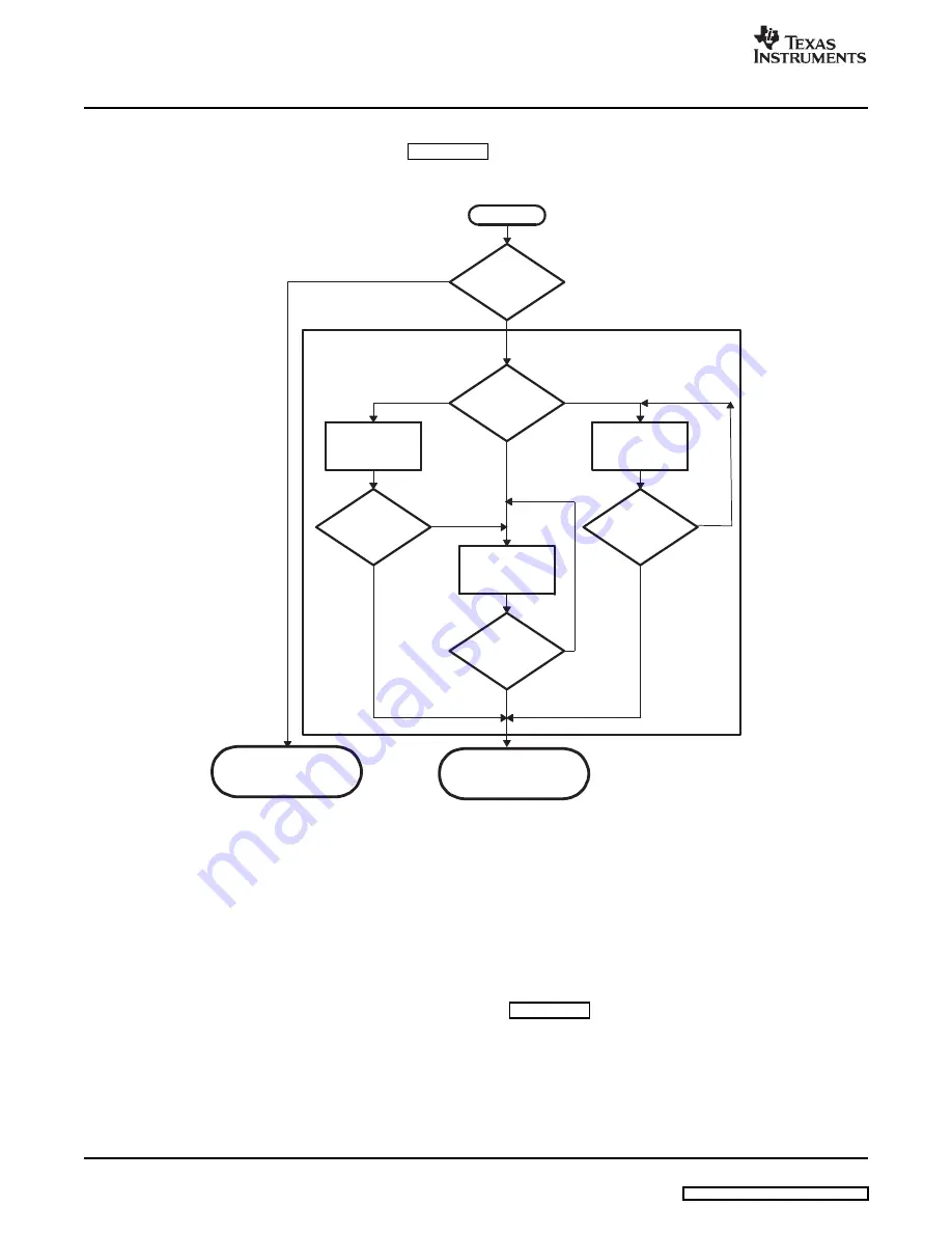
The general boot sequence is shown in
.
Figure 11-2. Boot Mode Functional Block Diagram
DM355’s ARM ROM boot loader (RBL) executes when the BOOTSEL[1:0] pins indicate a condition other
than the normal ARM EMIF boot (BTSEL[1:0]
≠
01). In this case, control is passed to the ROM boot loader
(RBL). The RBL then executes the proper mode after reading the state of the BTSEL[1:0] pins from the
BOOTCFG register.
If the value in BTSEL[1:0] from the BOOTCFG register is 00, the NAND mode executes. The outline of
operations followed in the NAND mode is described in
. The NAND boot mode assumes the
NAND is located on the EM_CE0 interface, whose bus configuration is configure by the pins AECFG[3:0].
The pins AECFG[3:0] must be configured such that the proper EMIF signals are availabel for the NAND
device.
152
Boot Modes
SPRUFB3 – September 2007


