System Overview
22
TIDUES1A – October 2019 – Revised February 2020
Copyright © 2019–2020, Texas Instruments Incorporated
EMC Compliant 10/100-Mbps Ethernet PHY Reference Design With IEEE
802.3at Type-1 (
≤
12.95 W) PoE-PD
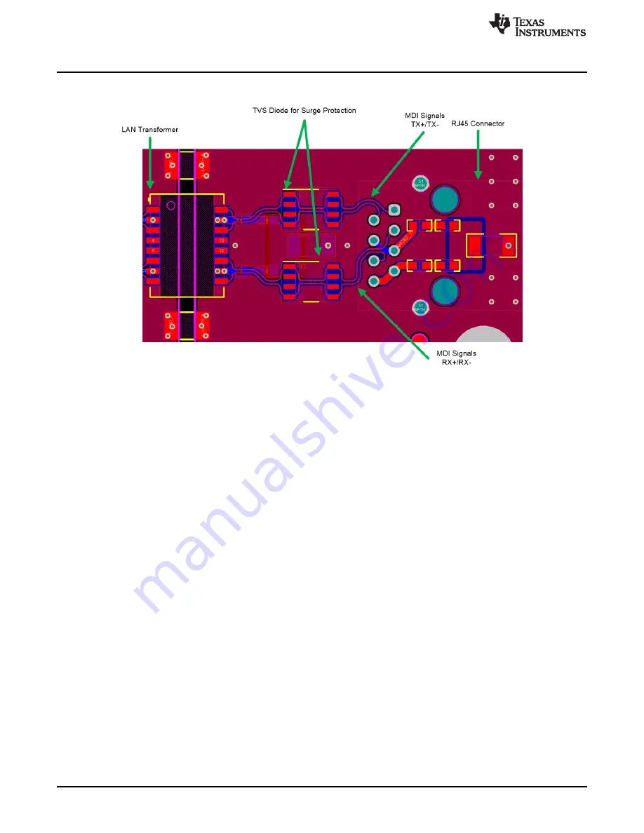
Figure 19. MDI Connections Between Isolation Transformer and RJ45 Connector
For EMI considerations, the following guidelines were used for this section of the circuit:
•
Congregate the input-related components toward the RJ45 input connector.
•
Use a metal shielded RJ45 connector, and connect the shield to chassis ground.
•
Use of magnetics with integrated common-mode choke is preferred.
•
The distance between the magnetic module and the RJ45 jack is the most critical and must always be
as short as possible (must be less than one inch).
•
Never use 90° traces. Use 45° angles or radius curves in traces.
•
The separation between the TX+/TX– and the RX+/RX– differential pairs must be at least 0.5 mm. It is
best to separate them with a ground plane.
•
MDI signals are differential. Within the pairs (for example, TX+/TX– or RX+/RX–) the trace lengths
should be run parallel to each other and matched in length. Matched lengths minimize delay
differences, avoiding an increase in common-mode noise and increased EMI. To ensure data integrity,
the trace length should be matched within ±50 mils, see
•
Do not overlap the circuit and chassis ground planes, keep them isolated. Connect chassis ground and
system ground together using two size 1206 0-
Ω
resistors across the void between the ground planes
on either side of the RJ45. These resistors can be removed or replaced with alternative components
(that is, capacitors or EMI beads) during system level certification testing, if necessary.
•
For non-PoE ports, include the 75-
Ω
as Bob Smith cable terminations at the center tap of the isolated
winding as
shows.
•
For PoE enabled ports, include the 75-
Ω
and 0.01-µF as Bob Smith cable terminations on the input
power lines at the center tap of the isolated winding as
and
show.
•
Include the 1000-pF, 2-kV bypass capacitor to tie the Bob-Smith cable terminations to a copper plane
(shield) which is commonly referred to as the Bob Smith plane (BS plane). Connect a 1000-pF, 2-kV
bypass capacitor to the Bob Smith plane using dedicated vias located directly at the capacitor
termination.
•
To maintain 1500-V
RMS
isolation between two adjacent layers of a NEMA FR-4 multi-layer PCB, a
minimum of 15 mils isolation thickness is recommended. This provides a safe margin for high-potential
requirements. The isolation thickness used in this design is 94 mils.
•
Use a number of perimeter vias to stitch the top and bottom layers of the Bob Smith plane together.
•
Additional capacitors are required to interconnect chassis ground and signal ground. The suggested


