1:1
Pin 9
(RD-)
Pin 10
(RD+)
Pin 11
(TD-)
Pin 12
(TD+)
3.3-V
Supply
1 F
0.1 F
3.3-V
Supply
1 F
0.1 F
3.3-V
Supply
49.9
Ÿ
49.9
Ÿ
49.9
Ÿ
49.9
Ÿ
RD -
RD +
TD -
TD +
RJ 45
1 F
0.1 F
1 F
0.1 F
1:1
System Overview
20
TIDUES1A – October 2019 – Revised February 2020
Copyright © 2019–2020, Texas Instruments Incorporated
EMC Compliant 10/100-Mbps Ethernet PHY Reference Design With IEEE
802.3at Type-1 (
≤
12.95 W) PoE-PD
–
Route MDI traces to the transformer on the same layer.
–
Never use 90° traces. Use 45° angles or radius curves in traces.
–
Keep PCB trace lengths as short as possible. Keeping the traces as short as possible also helps
reduce capacitive loading.
–
Avoid supplies and ground beneath the magnetics.
–
Do not overlap the circuit ground and chassis ground planes. Keep chassis ground and circuit
ground isolated by turning chassis ground into an isolated island by leaving a gap between the
planes. Connecting a 1206 (size) capacitor between chassis ground and circuit ground is
recommended to avoid floating metal. Capacitors less than 0805 (size) can create an arching path
for ESD due to a small air-gap.
–
Do not run signal traces such that they cross a plane split as
shows. A signal crossing a
plane split may cause unpredictable return path currents and would likely impact signal quality as
well, potentially creating EMI problems.
–
Avoid stubs on all signal traces, especially the differential signal pairs (see
).
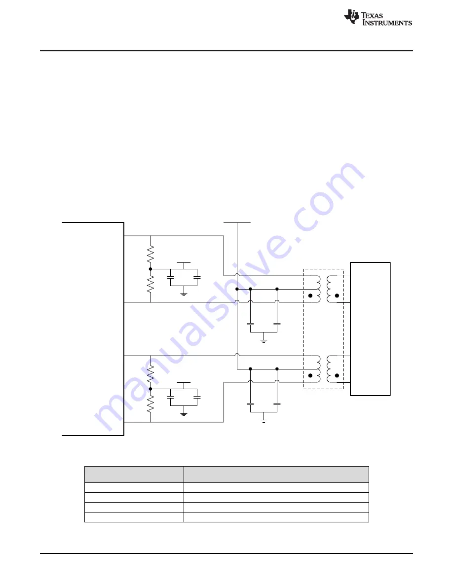
Figure 16. DP83822I TPI Network Interface
Table 7. Differential Signal Trace Length From DP83822I Ethernet PHY to
Magnetics on PSE Side Board
MDI DIFFERENTIAL PAIR NAME
TRACE LENGTHS FROM DP83822I ETHERNET PHY TO
MAGNETICS ON PSE SIDE BOARD
TD_IN_P
833.060 mils
TD_IN_N
831.054 mils
RD_IN_P
790.948 mils
RD_IN_N
793.119 mils


