www.ti.com
Installing the EVM Control Software and USB Driver
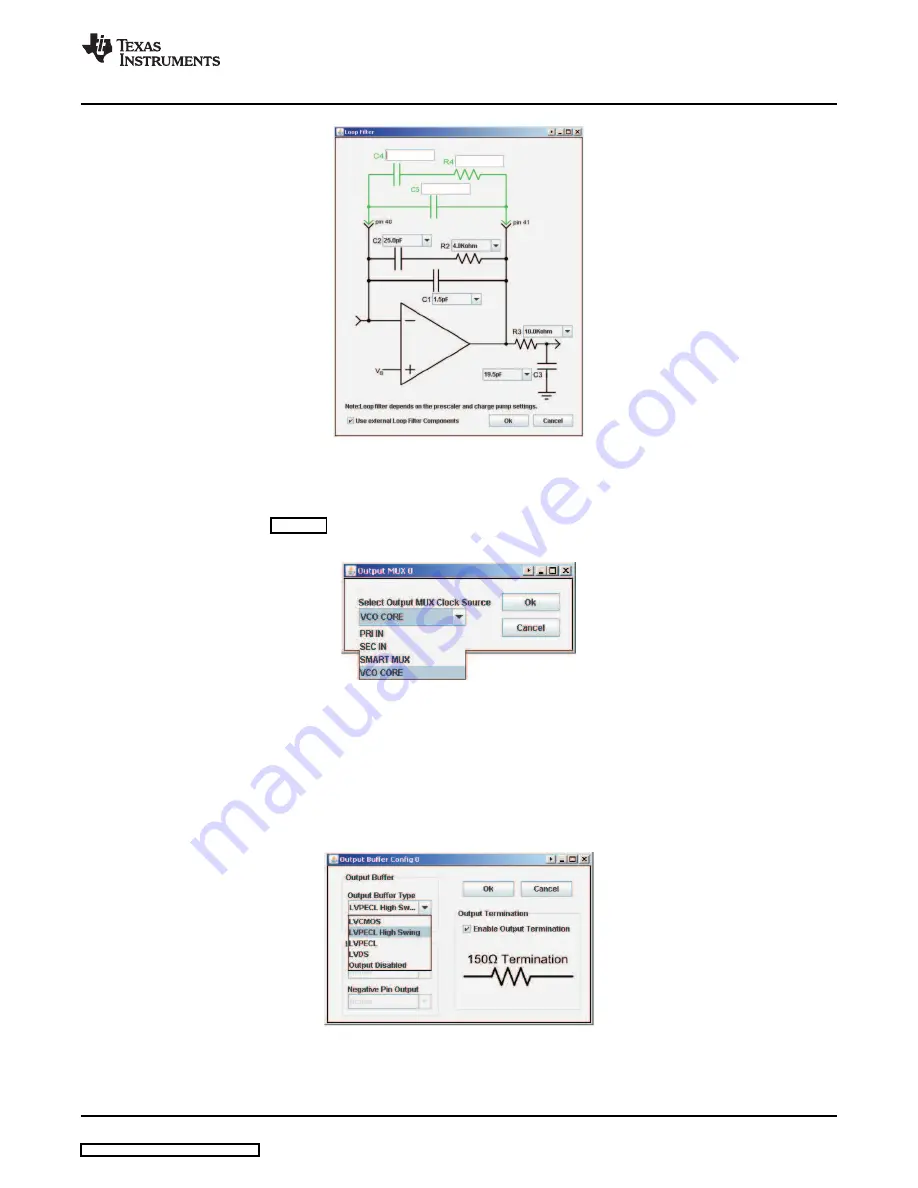
Figure 7. Loop Filter, Additional External Components
5.
Output MUX Selection
The Output MUX section of the EVMCS for each of the five outputs can be clicked to open a popup
window, shown in
, showing each Output MUX clock source. These are selectable between
the primary input, secondary input, Smart MUX output or the PLL VCO core output.
Figure 8. Output MUX (each output channel)
6.
Output Type Selection
The Output buffer section of the EVMCS for each of the five outputs can be clicked to open a popup
window that shows options for each output clock source. These are selectable between LVPECL, High
Swing LVPECL (in which cases the output 150
Ω
termination is automatically enabled), Reduced
Range Link LVDS, General Purpose Link LVDS, LVCMOS (in which case each of the P and N act as
two separate LVCMOS outputs with the same frequency that can either be active, inverting, tri-state or
low) or each output can be disabled.
Figure 9. Output Buffer Config (each output)
7.
PLL Dividers Selection
The input, feedback and prescaler dividers can be selected by clicking on tabs in the EVMCS which
SCAU024 – September 2008
Low Phase Noise Clock Evaluation Module — up to 1.5 GHz
7


