Termostroj
Croatia
APPENDIX - 3
Termo-Blok PTV-m
2. Electric sketch Termo-Blok PTV-m
3. Connection plate
Page 49
Page 1: ...m European Union ELECTRIC BOILERS FOR CENTRAL HEATING TERMO Blok TERMO Extra TERMO Blok PTV INSTRUCTIONS FOR USE Ulaganje u budućnost Investing for the future Projekt sufinancira Europska unija iz Europskog fonda za regionalni razvoj Project is co founded by the European Union s Regional Development Fond INSTRUCTIONS FOR USE We reserve the right of alternations ...
Page 2: ...TMS UT 0114 T03 1 INSTRUCTIONS FOR USE We reserve the right of alternations ...
Page 3: ...ection 5 1 6 1 Availability 5 1 6 2 Domestic water 5 1 6 3 Central heating 5 2 Using control panels 6 2 1 Working with standard control panel 6 2 2 Working with electronic control panels option E 7 2 3 Working with electronic control panels option C and W and Termo Blok PTV 8 2 3 1 General 8 2 3 2 Central heating functions 11 2 3 3 Domestic water functions control panel type 2 13 2 3 4 Central hea...
Page 4: ...offer you the possibility to reduce the power of a heater if necessary The power may be switched on when necessary automatically with the built in step regulator or manually with switches on the control board In this way it is possible to adapt the boiler to the utmost to circumstances on the spot The boiler operates on the principle of rapid heating smaller water quantities so that exploiting of ...
Page 5: ...urve if necessary Every heating room is built up differently Different heating elements and heating systems can be used radiators under floor heating or combined heating and every building has a different thermal insulation For the maximum exploitation of the heating and maximum energy savings characteristic heating curve has to be set using the parameter on the control panel in a way that the cho...
Page 6: ...C Room temperature is too low if the external temperature is between 5o C and 5o C Leave the curve 1 5 Add with offset 3oC Room temperature is too low if the external temperature is below 5o C Change with the first higher curve Leave offset 0o C Room temperature is too high if the external temperature is above 5o C Change with the first higher curve Lower with offset 6o C Room temperature is too h...
Page 7: ... desired water temperature in the boiler that is 25 C higher than set values of the desired domestic water temperature independent of central heating curve Circulation pump for domestic water conditioning supplies the container until the desired temperature of domestic water is reached upon which it is switched off with previously described and programmed time delay If the central heating is off e...
Page 8: ...hen the temperature sensor of warm water container reads the value below 7 C signaling switching on by blinking display as well as the LED diode of the heater and warm water conditioning regulating the warm water container temperature to 7 C 1 6 3 Central heating If the boiler is on for supply and heating or both heating and warm water conditioning are off the protection from freezing the water in...
Page 9: ...ower stage of boiler Boilers with 3 stages have soft start for the second and the third stage and switches 3 have only limiting function If the boiler is heating the light of heater in operation 8 is on if heaters are not working and boiler is in standby only ON OFF light is on Adjustment of desired temperature of central heating With the help of working thermostat 2 it is possible to select the f...
Page 10: ...ure of boiler adjustment of temperature 2 Signalization of operation degree of heaters 1 2 3 3 Signalization of the presence of air in the boiler red light 4 Signalization of under voltage protection red light 5 Signalization of boiler operation green light 6 Adjustment of temperature in boiler 7 Switch for central heating switching on and off 8 Thermal fuse Switching on of central heating By swit...
Page 11: ...atically continue the operation when the network voltage reaches values above 180V Cutout thermostat turning on Cutout thermostat safety thermostat 8 protects the boiler against rapid increase of temperature above 115 C The fuse turns off the boiler and ejects the RCCB RCD switch To continue the operation it is necessary to take off the protection cover from the cutout thermostat and press the red...
Page 12: ...n 4 0 2 bar 0 I 0 I OK AIR U 12 1 2 3 4 5 6 7 8 9 10 11 52 Type 2 Outdoor temperature compensation and sanitary water on Termo Extra or Termo Blok PTV 1 Display Display of temperatures values reading from KTY probes from 99oC above 99oC display is blinking up to 19o C below 19o C the display shows Display of desired temperature or curve during setup Following warning signals can be displayed INSTA...
Page 13: ...he air appears in the boiler the diode becomes red and at the same time the operation of the device is stopped After venting the diode automatically changes the color to green and operation of the boiler is continued 4 Led diode too low supply voltage If the net voltage falls below 170 V red light appears and at the same time the operation of the device is stopped 5 Led diode of central heating It...
Page 14: ...the key 6 user can limit the power level By pressing the key it is possible to select 1 2 or 3 as number of available power levels If the key is held pressed less than 5 s the selected power level mode will become active Boilers from 6 to 16 kW have only two power levels Limiting maximum temperature inside the boiler By pressing the key 6 user can limit maximum temperature inside the boiler Factor...
Page 15: ...e key 6 it is possible to change offset in steps of 1 C Factory setting is 0 C Offset range is from 9 to 20 C If the key is held pressed less than 5 s the displayed value becomes valid offset in C Setting the minimal temperature inside the boiler By pressing the key 6 user can select minimal temperature inside the boiler Minimal temperature starts blinking Factory setting is 27 C for radiator heat...
Page 16: ...g the desired temperature in domestic water storage By pressing the key 8 user can enter the domestic water temperature menu The desired water temperature in domestic water storage is blinking By pressing the key 8 the value of desired domestic water temperature in domestic water storage is changing in steps of 1 C If the key is held pressed less than 5 s the value from the display becomes the des...
Page 17: ...ioning is blinking By pressing the key the time is changing from 0 1 min up to 19 min with the step of 1 digit If the key is held pressed less than 5 s the value from a display becomes valid time of supplemental operation of circulation pump for domestic warm water conditioning Factory setting is 1 min Setting stand by temperature inside boiler By pressing the key 8 user can setup stand by tempera...
Page 18: ...he key 6 user can enter the boiler temperature menu The desired boiler temperature is blinking By pressing the key 6 UP or DOWN the desired boiler temperature can be set in steps of 1 C If the key is held pressed less than 5 s the value from the display becomes the desired boiler temperature Possible adjustment is from 20 C up to 90 C for radiator heating Possible adjustment is from 15 C up to 45 ...
Page 19: ...ulus If the boiler is not connected to the room thermostat or if the boiler is out of function during the winter time there is a danger of installation freezing In this case the system should be filled with antifreeze liquid for central heating and if this is not possible water should be drained out 3 2 Cleaning It is not permitted to use aggressive media e g gasoline kerosene or solvent for clean...
Page 20: ...there is an axis with the groove for screwdriver Using the screwdriver the pump 2 should be turned several times in the direction of the arrow on the pump head and the boiler should be put on again When the pump starts the operation the temperature of water in the boiler and the temperature of sanitary water should be selected The optimal temperature for central heating is between 60 and 70 C If t...
Page 21: ...lation pump does not operate air stopper on central heating installation prevents circulation start mechanical pump CHAPTER 4 deaerate installation boiler does not provide enough heat one phase is missing on supply in two stage thermostats the second stage is not functioning the second or the third stage is not manually turned on one switcher is defective a part of heater is burned through in a th...
Page 22: ...tch disconnects defective heater humidity on conductors safety thermostat is activated check leakage contact authorized service personnel to resolve the exact source of the problem RCCB switch cannot be reset safety thermostat is activated pre reset safety thermostat and then the RCCB switch contact authorized service personnel to resolve the exact source the of problem Ulaganje u budućnost Invest...
Page 23: ... o 10250 Lučko F Puškarića 1d Tel Fax 385 1 6531 008 6531 015 6531 016 Eurposka unija e mail info termostroj com web http www termostroj com European Union INSTALACIJSKE UPUTE Zadržavamo pravo izmjene uputa bez posebne najave ...
Page 24: ...n Union ELECTRIC BOILERS FOR CENTRAL HEATING TERMO Blok TERMO Extra TERMO Blok PTV INSTRUCTIONS FOR INSTALLATION Ulaganje u budućnost Investing for the future Projekt sufinancira Europska unija iz Europskog fonda za regionalni razvoj Project is co founded by the European Union s Regional Development Fond INSTRUCTIONS FOR INSTALLATION We reserve the right of alternations ...
Page 25: ...TMS UT 0114 T01 1 INSTRUCTIONS FOR INSTALLATION We reserve the right of alternations ...
Page 26: ...irements 14 3 1 Contents included in delivery 14 3 2 Preliminary remarks 14 3 3 Recommendations for various installation types 15 3 4 Installation site 15 3 4 1 Position of a boiler 15 3 4 2 Power supply 16 3 5 System requirements 16 3 5 1 Pipe work 16 3 5 2 Cleansing and flushing the system 16 3 5 3 Filling and preparing heating system 17 3 5 4 Pressure relief valve 17 3 5 5 Pressure gauge 17 3 5...
Page 27: ...nel 26 5 5 Working with electronic control panels option E 27 5 6 Working with electronic control panels option C and W and Termo Blok PTV 28 5 6 1 General 28 5 6 2 Central heating functions 30 5 6 3 Domestic water functions control panel type 2 32 5 6 4 Central heating functions with heating curves disabled 34 5 6 4 1 Access to special service menu 35 5 7 Starting the pump manually 36 6 Maintenan...
Page 28: ...RMO Extra and TERMO Blok boilers offer you a possibility to reduce the power of the heater if necessary The power may be switched on automatically when necessary with built in step regulator or manually with switches on the control board In this way it is possible to adapt the boiler to the utmost to circumstances on the spot The boiler operates on a principle of rapid heating smaller water quanti...
Page 29: ...on can adjust correct that curve if necessary Every heating room is built up differently Different heating elements and heating systems can be used radiators under floor or combined heating and every building has a different thermal insulation For the maximum exploitation of the heating and maximum energy savings characteristic heating curve has to be set using the parameter on the control panel i...
Page 30: ...rve Add with offset 6o C Room temperature is too low if the external temperature is between 5o C and 5o C Leave the curve 1 5 Add with offset 3oC Room temperature is too low if the external temperature is below 5o C Change with the first higher curve Leave offset 0o C Room temperature is too high if the external temperature is above 5o C Change with the first higher curve Lower with offset 6o C Ro...
Page 31: ... higher than set values of a desired domestic water temperature independent of the central heating curve Circulation pump for domestic water conditioning supplies container until the desired temperature of domestic water is reached upon which it is switched off with the previously described and programmed time delay If the central heating is off either floor or radiators heating at the moment of r...
Page 32: ... container reads the value below 7 C signaling switching on by blinking display as well as the LED diode of the heater and warm water conditioning regulating the warm wear container temperature to 7 C 1 6 3 Central heating If the boiler is on for supply and heating or both heating and warm water conditioning are off the protection from freezing of water in the central heating system switches autom...
Page 33: ... Expansion vessel L bar Dimensions mm Weight kg Maximum operating pressure MPa bar Pipes BSP male Power supply 6 6 8 0 8 A 330 B 930 C 290 D 100 E 65 F 320 40 0 25 2 5 3 4 400V 3N 50 60 Hz 9 12 14 16 18 10 10 0 8 A 400 B 930 C 290 D 150 E 65 F 305 46 1 20 22 24 28 22 12 0 8 A 474 B 930 C 290 D 226 E 65 F 305 53 32 36 40 Page 6 ...
Page 34: ...el L bar Dimensions mm Weight kg Maximum operating pressure MPa bar Pipes BSP male Power supply 6 10 8 0 8 A 400 B 930 C 290 D 150 E 65 F 150 G 50 H 305 48 0 25 2 5 3 4 DHW cylinder 1 heating 400V 3N 50 60 Hz 9 12 15 18 10 0 8 22 24 28 22 12 0 8 A 480 B 930 C 290 D 226 E 65 F 150 G 50 H 305 55 32 36 40 Page 7 ...
Page 35: ...Dimensions mm Weight kg Maximum operating pressure MPa bar Pipes BSP male Power supply 6 6 A 330 B 750 C 230 D 100 E 57 F 126 26 0 25 2 5 3 4 400V 3N 50 60 Hz 9 12 14 16 18 10 A 400 B 750 C 230 D 150 E 57 F 126 32 1 22 24 28 19 A 400 B 930 C 310 D 162 E 115 F 109 45 6 4 32 36 40 44 48 Page 8 ...
Page 36: ...S Power kW Capacity Lit Dimensions mm Weight kg Maximum operating pressure MPa bar Pipes BSP male Power supply 52 19 A 400 B 930 C 310 D 162 E 115 F 109 45 0 25 2 5 6 4 400V 3N 50 60 Hz 56 60 64 32 A 550 B 930 C 310 D 316 E 115 F 175 72 2 72 80 88 96 Page 9 ...
Page 37: ... capacity Icn IEC 947 2 Min conductor s cross section Fuse type RCCB switch type 400V 3N 50 60 Hz 6 kW 8 70 A 10 A 10 kA 15 kA 5 x 2 5 mm2 B10 3 25 0 03 A 9 kW 13 04 A 16 A B16 3 12 kW 17 39 A 25 A 5 x 4 mm2 B25 3 14 kW 20 29 A 16 kW 23 19 A 32 A B32 3 18 kW 26 09 A 5 x 6 mm2 40 0 03 A 20 kW 28 99 A 40 A B40 3 22 kW 31 88 A 24 kW 34 78 A 5 x 10 mm2 28 kW 40 58 A 50 A B50 3 63 0 03 A 0 3A Termo Ext...
Page 38: ...low 11 Circulation pump 3 External boiler jacket 12 Safety valve on 2 5 bars 4 Boiler 13 Automatic venting pot 5 Heat insulation 14 Charge and discharge valve 6 Electrical heaters 15 Boiler venting valve 7 Control panel 16 Air indicator 8 Inducers for el connections 17 Splitter 9 Contactors 18 RCCB switch Page 11 ...
Page 39: ...3 Automatic venting valve 4 Boiler 14 Charge and discharge valve 5 Heat insulation 15 Manual venting valve 6 Electrical heaters 16 Air indicator 7 Control panel 17 Splitter 8 Inducers for el connections 18 RCCB switch 9 Contactors 19 Pump for domestic water cylinder 10 Expansion vessel 20 Primary flow for domestic water cylinder Page 12 ...
Page 40: ...01 1 TERMO Extra 1 Primary flow 6 Electrical heaters 2 Return flow 7 Control panel 3 External boiler jacket 8 Inducers for el Connections 4 Boiler 9 Contactors 5 Heat insulation 10 Charge and discharge valve Page 13 ...
Page 41: ...ions C W and Termo Blok boilers with option C Item 5 is only delivered for Termo Extra boilers with option W and Termo Blok PTV boilers In the case of boilers with the power of 6 7 kW additional jumpers are provided in order to enable single phase power supply connection for the boiler 3 2 Preliminary remarks When connecting the appliance to the fixing wiring the means for disconnection MCB must b...
Page 42: ...nstalation type Termo BlokPTV m Appendix 3 or Termo Extra m Appendix 4 Termo Extra m Appendix 4 New installation Existing installation Control panel Instalation type Electronic control panel Basic control panel Termo Blok e Appendix 5 or Termo Extra e Appendix 6 Termo Extra e Appendix 6 New installation Existing installation Instalation type Termo Blok m Appendix 7 or Termo Extra m Appendix 8 Term...
Page 43: ...a boiler Note In some cases additional measures must be taken subject to the requirements of the Local Authorities 3 5 System requirements 3 5 1 Pipe work Pipe work that is not a forming part of the useful heating surface should be insulated to help prevent heat loss and possible freezing particularly where pipes are run through roof spaces and ventilated under floor spaces Draining taps must be l...
Page 44: ...urposes 3 5 5 Pressure gauge This is factory fitted to the Termo Blok and Termo Blok PTV boiler and indicates the primary circuit pressure to facilitate filling and testing In the case of Termo Extra boiler pressure gauge must be fitted to the installation 3 5 6 Expansion vessel Termo Blok and Termo Blok PTV boilers incorporate an expansion vessel Refer to chapter 2 1 for more information about in...
Page 45: ...d movements during a two person lift to ensure equal spread of weight of load It is recommended to wear suitable cut resistant gloves with good grip to protect against sharp edges and ensure good grip when handling appliance 4 2 Select position for boiler Refer to chapter 3 4 1 for information regarding the appliance position In general the boiler must be positioned in such manner that There is en...
Page 46: ...rements before proceeding System flushing is necessary in order to prevent damage to appliance It is recommended to fit valves on flow and return pipe work in order to enable easy disconnection separation of boiler from the central heating system The following figure indicates flow and return for the central heating on Termo Extra Termo Blok and Termo Blok PTV boilers TERMO Extra TERMO Blok Termo ...
Page 47: ...M6 and pulling protection cover out Power cable must be connected directly to RCCB RCD earth must be connected to separate terminal 3 After connecting power cable protective cover 1 must be put in place and tighten Power supply connection RCCB RCD connection close up Note Power cables from Ø12 mm to Ø20 mm must be connected from bottom side of boiler with the use of provided plastic inducer for el...
Page 48: ...l testing resistor must be removed and wires from external temperature sensor must be connected protective cover base External temperature sensor External temperature sensor connection point on boiler s connection plate Note For connecting external temperature sensor two wire cable can be used of diameter from 0 6mm2 to 1 5 mm2 4 7 3 Connecting domestic hot water temperature sensor This is applica...
Page 49: ...inder temperature sensor Water cylinder temperature sensor connection point on boiler s connection plate Note For connecting water cylinder temperature sensor two wire cable of diameter from 0 6mm2 to 0 75 mm2 can be used Page 22 ...
Page 50: ...foss TP9 Terminals 4 and L power supply for control unit are linked together If external control unit is used this link must be removed Note For more details see selected appendix from chapter 3 3 Connection plate type 1 Connection plate type 2 4 7 5 Connecting external pump on Termo Extra boilers Terminals L N PE for external pump connection HW PUMP are located on connection plate Connection plat...
Page 51: ...t at 45ºC Pin 1 OFF Factory settings Set heating type to radiator curves from 1 to 3 are active minimum boiler temperature is set at 25ºC maximum boiler temperature is set at 90ºC Pin 2 OFF Disable outdoor temperature compensation the user must manually select temperature in boiler Pin 2 ON Factory settings Enable outdoor temperature compensation default curve for radiator heating is 1 5 and 0 6 f...
Page 52: ...L3 L2 L3 L1 N If there is no voltage between any combinations of phases one phase is missing and the heating elements inside the appliance can be damaged If the voltage between phases is 10 higher than nominal voltage of the appliance the appliance itself can be damaged For all systems Check if fixed wiring system is used and that MCB is installed and conform to chapter 2 2 or 2 3 Check if the use...
Page 53: ...lp of working thermostat 2 it is possible to select a fixed desired temperature in boiler Working thermostat range from 20ºC to 90ºC Recommended temperature is about 60ºC 12 clock position Air in the boiler 5 red light If the air appears in the boiler the signalization of air in the boiler turns on 5 and the boiler operation stops In this way the boiler is protected against burning through due to ...
Page 54: ... displayed 1 if the current temperature in boiler meets the desired one the signalization lamp of boiler operation 5 is switched off Adjustment of desired temperature of central heating By pressing the key for temperature adjustment 6 the desired temperature in the boiler appears the signalization lamp of boiler operation 5 is twinkling By repeated pressing upwards or downwards it is possible to i...
Page 55: ... Working with electronic control panels option C and W and Termo Blok PTV 5 6 1 General Regardless of the selected regulation curve the maximum water temperature in the boiler is limited to 90 C for radiator heating and 50 C for floor heating Factory setting of the curve is 1 5 for radiator heating Factory setting of the curve is 0 6 for underfloor heating Refer to chapter 1 4 for detailed descrip...
Page 56: ...ed on the display as a running light 12 Safety thermostat 2 Led diodes of heaters stages The number of lighted diodes corresponds to the number of currently active heater stages up to seven 3 Led diode OK air in boiler If there is no air in the boiler the diode lights green If the air appears in the boiler the diode lights red and at the same time the operation of the device is stopped After venti...
Page 57: ... key curve number changes in increment of 0 1 within the set according to the diagram on the front panel If the key is depressed for more than 5s value on the display will be memorized and becomes active Radiator heating Adjustment range 1 3 factory default 1 5 Underfloor heating Adjustment range 0 2 0 9 factory default 0 6 Manual setting of wanted boiler temperature By pressing the key 6 user can...
Page 58: ... user can enter the curve selection menu The LED display will show current offset in C Offset does not affect maximal or minimal temperature they are set in absolute values By pressing the key 6 it is possible to change offset in steps of 1 C Adjustment range 9 to 20 C Factory default 0 C If the key is depressed for more than 5s value on the display will be memorized and becomes active Reset to fa...
Page 59: ... key 8 user can enter the domestic water temperature menu The desired water temperature in domestic water storage is blinking By pressing the key 8 the value of desired domestic water temperature in domestic water storage is changing in steps of 1 C If the key is held pressed less than 5 s the value from the display becomes the desired domestic water temperature Possible adjustment is from 10 C up...
Page 60: ...itioning is blinking By pressing the key the time is changing from 0 1 min up to 19 min In increment of 0 1 If the key is depressed for more than 5s value on the display will be memorized and becomes active Factory default 1 min Setting standby boiler temperature By pressing the key 8 user can setup stand by boiler temperature Display will show current standby boiler temperature Pressing the key 8...
Page 61: ... pressing the key 6 user can enter the boiler temperature menu The desired boiler temperature is blinking By pressing the key 6 UP or DOWN the desired boiler temperature can be set in steps of 1 C If the key is held pressed less than 5 s the value from the display becomes the desired boiler temperature Possible adjustment is from 20 C up to 90 C for radiator heating Possible adjustment is from 15 ...
Page 62: ... becomes active Radiator heating Adjustment range 20 C 45 C factory default 45 C Underfloor heating Adjustment range 15 C 30 C factory default 30 C Setting the central heating pump delay By pressing key 6 user can change pump delay time between 0 15 min Factory settings is 0 Selecting the time delay between steps for power regulation By pressing the key 6 user can change the time delay between ste...
Page 63: ...illed up valves and general functionality of the device should be checked RCCD switch pressing the TEST button must disconnect the RCCD switch This testing procedure insures that switch is functioning properly We recommend this test once or twice in heating season Safety thermostat we recommended to check safety thermostat before every heating season by heating up the sensor with heating fan or li...
Page 64: ...al heating installation prevents circulation start mechanical pump CHAPTER 4 deaerate installation boiler does not provide enough heat one phase is missing on supply in two stage thermostats the second stage is not functioning the second or the third stage is not manually turned on one switcher is defective a part of heater is burned through in a three phase system the three different phases are n...
Page 65: ...esolve the exact source of the problem RCCB switch disconnects defective heater humidity on conductors safety thermostat is activated check leakage contact authorized service personnel to resolve the exact source of the problem RCCB switch cannot be reset safety thermostat is activated pre reset safety thermostat and then the RCCB switch contact authorized service personnel to resolve the exact so...
Page 66: ...TMS UT 0114 T01 1 Page 39 ...
Page 67: ...d automatically adjusts the temperature level in the boiler radiators or under floor heating system It is very simple to adjust the building or apartment insulations characteristics on the control panel Sanitary water probe supplied must be installed into the water cylinder because the control panel needs information about domestic water temperature level Domestic hot water has priority Room stat ...
Page 68: ... from the periods for preparing sanitary hot water The switches 7 and 9 on the electronic control panel have different functions when a seven day control unit for central heating and sanitary water preparing is installed In this case the position 0 is AUTO and the position 1 is MANUAL When sanitary water and apartment temperature rise to the desired level the boiler automatically goes to the stand...
Page 69: ...Termostroj Croatia APPENDIX 1 Termo Blok PTV 2 Electric sketch Termo Blok PTV e sample 1 2 1 Electric sketch Termo Blok PTV e sample 1 1 Page 42 ...
Page 70: ...ode too low supply voltage 5 Led diode of central heating 6 Push button for the adjustment of heating characteristics 7 Switch heating AUTOMATIC MANUAL 8 Push button for adjusting characteristics of sanitary water conditioning 9 Sanitary water conditioning AUTOMATIC MANUAL 10 Led diode in course of sanitary water conditioning 11 Indicator of water pressure in the heating system 12 Safety thermosta...
Page 71: ...ion with outside temperature probe and automatically adjusts the temperature level in the boiler radiators or under floor heating system It is very simple to adjust the building or apartment insulations characteristics on the control panel Sanitary water probe supplied must be installed into the water cylinder because the control panel needs information about domestic water temperature level Domes...
Page 72: ...eating program from the periods for preparing sanitary hot water The switches 7 and 9 on electronic control panel have a different function when 7 day control unit for central heating and sanitary water preparing is installed In this case position 0 is AUTO and position 1 is MANUAL When sanitary water and apartment temperature rise to the desired level the boiler automatically goes to standby posi...
Page 73: ...Termostroj Croatia APPENDIX 2 Termo Extra e 2 Electric sketch Termo Extra e sample 2 2 1 Electric sketch Termo Extra e sample 2 1 Page 46 ...
Page 74: ...ed diode too low supply voltage 5 Led diode of central heating 6 Push button for adjustment of heating characteristics 7 Switch heating AUTOMATIC MANUAL 8 Push button for adjusting characteristics of sanitary water conditioning 9 Sanitary water conditioning AUTOMATIC MANUAL 10 Led diode in course of sanitary water conditioning 11 Indicator of water pressure in heating system 12 Safety thermostat P...
Page 75: ...and cylinder With central heating programmer Danfoss TP 9 7 day programmer or similar you have an opportunity to separate the periods of central heating program from the periods for preparing sanitary hot water Domestic hot water can have priority or does not have to Room stat is recommended By using the room stat you can program several periods in a day via day temperature or reduced temperature ...
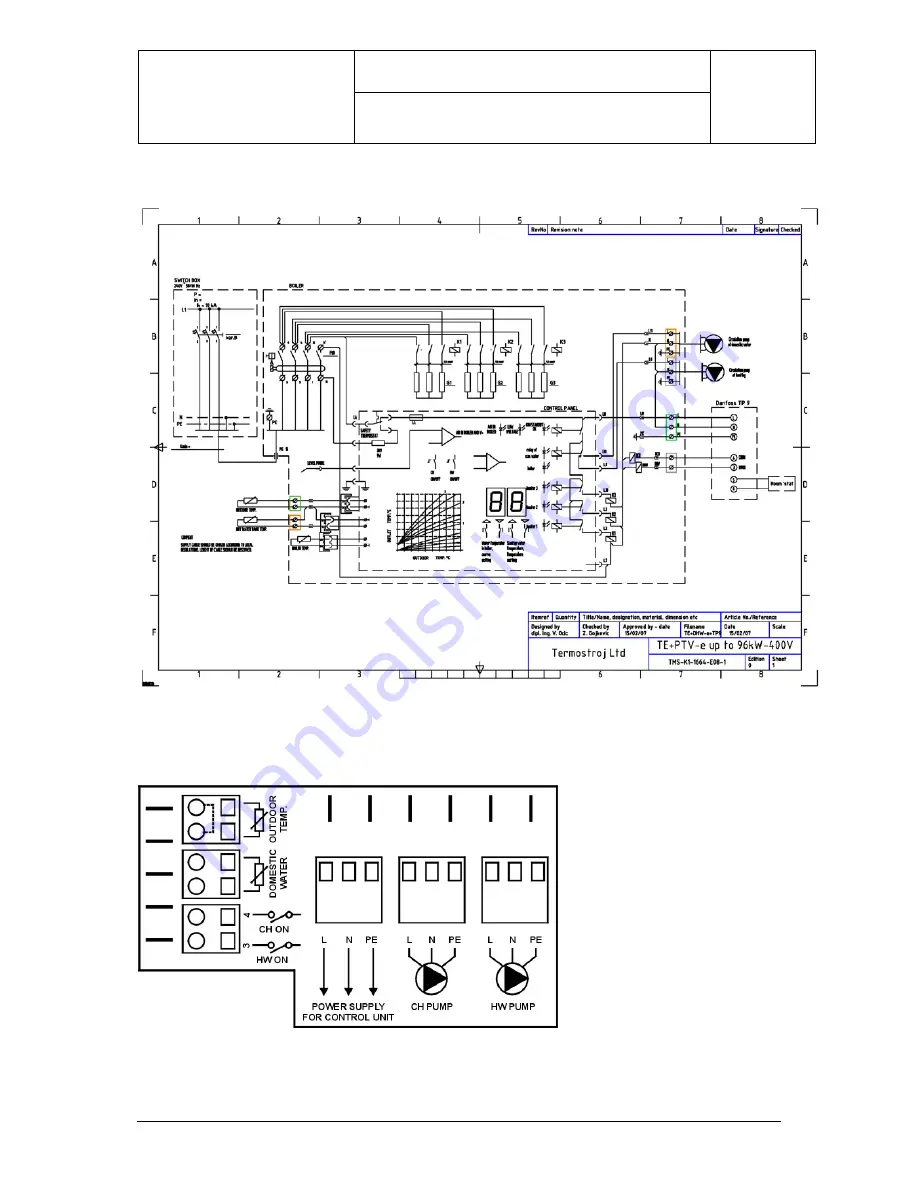
Page 76: ...Termostroj Croatia APPENDIX 3 Termo Blok PTV m 2 Electric sketch Termo Blok PTV m 3 Connection plate Page 49 ...
Page 77: ... capillary thermostat 3 SWITCH FOR THE 2ND AND 3RD OPERATION STAGE 4 LIMITING THERMOSTATE WITH MANUAL DEACTIVATION switches off on ca 115 oC 5 INDICATOR OF AIR APPEARANCE IN THE BOILER air indicator 6 SWITCH FOR AUTOMATICS FEEDING WITH 220V 1ST OPERATION STAGE 7 GLAS FUSE 2 5A PROTECTING THE PUMP AND SWITCHES 8 INDICATION OF HEATER OPERATION 9 INDICATES LOW VOLTAGE PROTECTION UNDER 180V Page 50 ...
Page 78: ... panel uses capillary thermostats to regulate temperature in the boiler and cylinder With central heating programmer Danfoss TP 9 7 day programmer or similar you have an opportunity to separate the periods of central heating program from the periods for preparing sanitary hot water Domestic hot water can have priority or does not have to Room stat is recommended By using the room stat you can prog...
Page 79: ... same sample as sample 4 but without programmer Room stat is recommended Using the room stat you can program several periods in a day with day temperature or reduced temperature level but you cannot program the period of preparing DHW The temperature of domestic hot water is on the desired level all the time Page 52 ...
Page 80: ...Termostroj Croatia APPENDIX 4 Termo Extra m 2 Electric sketch Termo Extra m sample 4 3 Connection plate sample 4 3 1 Connection plate sample 4 1 Page 53 ...
Page 81: ...illary thermostat 3 SWITCH FOR THE 2ND AND 3RD OPERATION STAGE 4 LIMITING THERMOSTATE WITH MANUAL DEACTIVATION switches off on ca 115 o C 5 INDICATOR OF AIR APPEARANCE IN THE BOILER air indicator 6 SWITCH FOR AUTOMATICS FEEDING WITH 220V 1ST OPERATION STAGE 7 GLAS FUSE 2 5A PROTECTING THE PUMP AND SWITCHES 8 INDICATION OF HEATER OPERATION 9 INDICATES LOW VOLTAGE PROTECTION UNDER 180V Page 54 ...
Page 82: ...trol panel uses the outside temperature information with outside temperature probe and automatically adjusts the temperature level in the boiler radiators or under floor heating system It is very simple to adjust the building or apartment insulations characteristics on the control panel Room stat is recommended By using the room stat you can program several periods in a day via day temperature or ...
Page 83: ...Termostroj Croatia APPENDIX 5 Termo Blok e 2 Electric sketch Termo Blok e 3 Connection plate Page 56 ...
Page 84: ...odes of heaters stages 3 Led diode OK air standby 4 Led diode too low supply voltage 5 Led diode of central heating 6 Push button for the adjustment of heating characteristics 7 Switch heating AUTOMATIC MANUAL 11 Indicator of water pressure in the heating system 12 Safety thermostat Page 57 ...
Page 85: ...ntrol panel uses the outside temperature information with outside temperature probe and automatically adjusts the temperature level in the boiler radiators or under floor heating system It is very simple to adjust the building or apartment insulations characteristics on the control panel Room stat is recommended By using the room stat you can program several periods in a day via day temperature or...
Page 86: ...Termostroj Croatia APPENDIX 6 Termo Extra e 2 Electric sketch Termo Extra e 3 Connection plate Page 59 ...
Page 87: ...iodes of heaters stages 3 Led diode OK air standby 4 Led diode too low supply voltage 5 Led diode of central heating 6 Push button for the adjustment of heating characteristics 7 Switch heating AUTOMATIC MANUAL 11 Indicator of water pressure in the heating system 12 Safety thermostat Page 60 ...
Page 88: ...ple 7 Basic characteristics This is a sample of central heating system Termo Blok type boilers have power range from 6 up to 40 kW Electromechanical control panel uses the capillary thermostats to regulate temperature in the boiler Room stat is recommended Using the room stat you can program several periods in a day with day temperature or reduced temperature level Page 61 ...
Page 89: ...Termostroj Croatia APPENDIX 7 Termo Blok m 2 Electric sketch Termo Blok m 3 Connection plate Page 62 ...
Page 90: ...llary thermostat 3 SWITCH FOR THE 2ND AND 3RD OPERATION STAGE 4 LIMITING THERMOSTATE WITH MANUAL DEACTIVATION switches off on ca 115 oC 5 INDICATOR OF AIR APPEARANCE IN THE BOILER air indicator 6 SWITCH FOR AUTOMATICS FEEDING WITH 220V 1ST OPERATION STAGE 7 GLAS FUSE 2 5A PROTECTING THE PUMP AND SWITCHES 8 INDICATION OF HEATER OPERATION 9 INDICATES LOW VOLTAGE PROTECTION UNDER 180V Page 63 ...
Page 91: ...mple 8 Basic characteristics This is a sample of central heating system Termo Extra type boilers have power range from 6 up to 96 kW Electromechanical control panel uses the capillary thermostats to regulate temperature in the boiler Room stat is recommended Using the room stat you can program several periods in a day with day temperature or reduced temperature level Page 64 ...
Page 92: ...Termostroj Croatia APPENDIX 8 Termo Extra m 2 Electric sketch Termo Extra m 3 Connection plate Page 65 ...
Page 93: ...illary thermostat 3 SWITCH FOR THE 2ND AND 3RD OPERATION STAGE 4 LIMITING THERMOSTATE WITH MANUAL DEACTIVATION switches off on ca 115 oC 5 INDICATOR OF AIR APPEARANCE IN THE BOILER air indicator 6 SWITCH FOR AUTOMATICS FEEDING WITH 220V 1ST OPERATION STAGE 7 GLAS FUSE 2 5A PROTECTING THE PUMP AND SWITCHES 8 INDICATION OF HEATER OPERATION 9 INDICATES LOW VOLTAGE PROTECTION UNDER 180V Page 66 ...
Page 94: ...al system used for preparing DHW in cylinder with a heat exchanger Termo Blok type boilers have power range from 6 up to 40 kW If you need more power you can use Termo Extra type boilers with max power 96 kW The capacity of cylinder that you can use is from 80 up to 5 000 lit Electromechanical control panel uses the capillary thermostats to regulate temperature in the boiler Recommended boiler tem...
Page 95: ...Fax 385 1 6531 008 6531 015 6531 016 Eurposka unija e mail info termostroj com web http www termostroj com European Union 2 Electric sketch Termo Blok m with DHW cylinder 3 Connection plate INSTALACIJSKE UPUTE Zadržavamo pravo izmjene uputa bez posebne najave ...
Page 96: ...E 4 LIMITING THERMOSTATE WITH MANUAL DEACTIVATION switches off on ca 115 o C 5 INDICATOR OF AIR APPEARANCE IN THE BOILER air indicator 6 SWITCH FOR AUTOMATICS FEEDING WITH 220V 1ST OPERATION STAGE 7 GLAS FUSE 2 5A PROTECTING THE PUMP AND SWITCHES 8 INDICATION OF HEATER OPERATION 9 INDICATES LOW VOLTAGE PROTECTION UNDER 180V Ulaganje u budućnost Investing for the future Projekt sufinancira Europska...
Page 97: ...Termostroj Croatia APPENDIX 9 Termo Blok m with DHW cylinder INSTALACIJSKE UPUTE Zadržavamo pravo izmjene uputa bez posebne najave ...
Page 98: ...on ELECTRIC BOILER FOR CENTRAL HEATING AND WARM WATER PREPARATION TERMO Kombi USER S INSTRUCTIONS Ulaganje u budućnost Investing for the future Projekt sufinancira Europska unija iz Europskog fonda za regionalni razvoj Project is co founded by the European Union s Regional Development Fond We reserve the right of changing these instructions without special prior notification ...
Page 99: ... contents 1 Introduction 1 2 About the product 1 2 1 Construction 1 2 2 Integral parts of the TERMO Kombi Boiler 2 3 Installation 3 3 1 Important warnings 3 3 2 Assembly 3 3 2 Assembly Continued 4 3 3 Connection to the power network 5 3 4 Connection of room thermostat 5 4 Use of the product 6 4 1 Use of the boiler 7 4 2 Manipulation with automatic equipment 8 4 4 Recommendations for optimal use 11...
Page 100: ... economic boiler for central heating and sanitary water preparation that may be used as the independent source of heat The boiler is operated on the principle of rapid heating smaller water quantities and its energy exploitation is almost 100 TERMO Kombi is suitable for using in smaller business premises flats smaller catering objects etc where it is important that it takes up small space Temperat...
Page 101: ...pansion vessel 11 Central heating pump 12 Safety valve at 3 bar 13 Automatic venting pot 14 Filling and emptying valve in packing it should be built in at installation 15 Valve for boiler venting 16 Sounding tube for air appearance control 17 Distributor 18 RCCB switch 19 Temperature sensor of sanitary water outlet line 20 Exchanger 21 Temperature sensor of sanitary water inlet line 22 Non return ...
Page 102: ...ING IN AREAS WITH STRONG CONCENTRATION OF LIME IT IS RECOMMENDED TO BUILD IN A MAGNETIC OR ELECTROMAGNETIC LIME BREAKER ON THE INLET LINE OF SANITARY WATER ON THE BOILER 3 2 Assembly TERMO Kombi is foreseen for the wall assembly and for the easier assembly on the backside there is foreseen the suspension support For the suspension you may use metal wall plugs with the screw M8 or M10 or stronger p...
Page 103: ...ent the water circle on upper side of Termo Kombi Protection cap should be release on automatic venting pots 1 and 2 Plastic pipe should be attached to valve 3 prior venting the water circle On the illustration you can see RCCG switch 1 contactors 2 capillary thermostat for prevent overheating during prepare sanitary hot water 3 and connection plate 4 for connecting pumps room stat and all probes ...
Page 104: ... if we connect it we have to take account of the fact which type of a room thermostat is to be connected One group of thermostats is connected only serially in the control voltage circuit resp on clamps The other group of thermostats has built in temperature simulation system and therefore should be constantly under voltage and according to the fixed temperature in the room on its outlet we have t...
Page 105: ...ignalization of air appearance in the boiler red light 4 Signalization of under voltage protection red light 5 Signalization of boiler operation green light 6 Adjustment of temperature in boiler 7 Switch for central heating switching on and off 8 Sanitary water temperature adjustment 9 Switch for switching on and off the sanitary water preparation 10 Signalization of sanitary water preparation and...
Page 106: ... manually started Circulation pumps lubricate bearings with water flowing through the pump and after stoppage it could occur that the bearings burn Starting the pump For starting the pump it is necessary to turn off the protection plug on its front side 1 below which there is the axis with the groove for screwdriver With the screwdriver the pump 2 should be several times turned in direction of the...
Page 107: ...e in order that the boiler memorizes a new temperature Use of sanitary water If there is a need for sanitary water the signalization lamp of sanitary water preparation turns on 10 and the temperature of warm water outlet displays Signalization of operation degree of heaters 2 displays and by turning on lamps it is shown whether one group of heaters is in operation two or all three groups The boile...
Page 108: ...škarića 1d Tel Fax 385 1 6531 008 6531 015 6531 016 Eurposka unija e mail info termostroj com web http www termostroj com European Union We reserve the right of changing these instructions without special prior notification TMS UT 1203 Z07 2 9 ...
Page 109: ...ce of air For continuation of operation the boiler should be vented If the boiler is correctly vented the operation of boiler continues automatically Voltage drop 4 red light If the voltage in the network line drops below 180V by phase the signalization of under voltage protection 4 turns on the boiler automatically switches off in order to protect electronics and contactors inside the boiler The ...
Page 110: ...of a device once a year by the authorized service before heating season This service is not included in the guarantee During the inspection all electric and water connections should be tightened the system should be vented and if necessary filled up valves and general functionality of the device should be checked If you notice a reduced effect of warm water it is necessary to remove lime accumulat...
Page 111: ...85 1 6531 008 6531 015 6531 016 Eurposka unija e mail info termostroj com web http www termostroj com European Union Schematic illustration of lime removal We reserve the right of changing these instructions without special prior notification TMS UT 1203 Z07 2 12 ...
Page 112: ...eration air blockage on central heating installation that prevents the circulation start the mechanical pump or replace it with the new one if it is blown see 4 1 vent the installation the boiler heats poorly on the feed one phase is missing in two phase thermostats second phase is not in operation second or third phase was not manually turned on one contactor defective a part of the heater has bl...
Page 113: ...switch can not be reset safety thermostat activated firstly reset the safety thermostat and then the FID switch sanitary water temperature is varying too low pressure or too small flow in plumbing installation set the warm water temperature to the desired temperature without mixing with cold water boiler does not reach a desired warm water temperature check network fuses warm water flow is higher ...
Page 114: ...0V 50Hz TERMO Kombi Boilers Type of the device Characteristics Units TERMO Kombi 18 TERMO Kombi 24 TERMO Kombi 32 TERMO Kombi 40 Central heating heat effect kW 18 24 32 40 Warm water heat effect kW 18 24 32 40 Max pump supply at 1000 lit h m 4 8 4 8 4 8 4 8 Area of central heating temperature adjustment oC 40 90 40 90 40 90 40 90 Area of warm water temperature adjustment o C 30 55 30 55 30 55 30 5...
Page 115: ...cuit breaking capacity Icn EN 60898 Rated short circuit breaking capacity Icn IEC 947 2 min conductor s cross section mm2 Schrak fuses type RCCB switch type 18 kW 27 35 A 32 A Kar B 10 kA 15 kA 6 B 32 3 63 0 03 A 24 kW 36 45 A 40 A Kar B 10 B40 3 32 kW 48 62 A 63 A Kar B B 63 3 40 kW 60 76 A Ulaganje u budućnost Investing for the future Projekt sufinancira Europska unija iz Europskog fonda za regi...
Page 116: ... o 10250 Lučko F Puškarića 1d Tel Fax 385 1 6531 008 6531 015 6531 016 Eurposka unija e mail info termostroj com web http www termostroj com European Union INSTALACIJSKE UPUTE Zadržavamo pravo izmjene uputa bez posebne najave ...