Terex TR100 Operation Manual Download Page 83

4-3

Operating the Truck

OPERATING THE TRUCK

Pre-Starting Inspection

*

Make sure all safety signs are free of  damage, and are fully
readable, replace as necessary.

*

Before the engine is started ensure the machine is ready for  operation.

*

The machine should be in a level position to permit accurate checking of
fluid quantities in the engine and other components.

*

Make sure


parking brake is applied and block wheels securely to prevent

accidental movement of the machine while checking component levels.

*

Test all lights, warning signals, controls and instruments for  proper
operation.

*

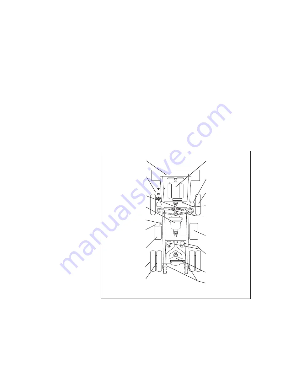
Walk around the machine and carry out the Inspections and Component
Checks described in the drawing and on the following pages.

2125

ENGINE

Check oil level. Check for

leaks.

FRONT RIDE CYLINDERS

Check for debris, leaks and

damage.

WHEELS AND TYRES

Check condition, inflation,

nuts and for damaged rims.

RADIATOR HEADER TANK

Check coolant level.

STEERING CYLINDERS

Check for debris, leaks and

damage. Check lines

for wear and leaks.

FUEL TANK

Check fuel level. Ensure fuel

tank is full.

BODY CYLINDERS

Check for debris, leaks and

damage. Check lines for

wear and leaks.

DIFFERENTIAL

Check for leaks.

REAR RIDE CYLINDERS

Check for debris, leaks and

damage.

RADIATOR AND COOLING

LINES

Check for leaks.

CAB, PLATFORM AND STEPS

Check for cleanliness. Check

seat belts.

BRAKE ACCUMULATORS

Check for leaks.

TRANSMISSION

Check oil level. Check

 for leaks.

STEERING ACCUMULATOR

Check for leaks.

STEERING AND
BRAKING TANK

Check oil level. Check for

leaks.

BODY AND DISC

BRAKE COOLING TANK

Check oil level. Check for

leaks.

WHEEL PLANETARIES

Check for leaks.

DISC BRAKE ASSEMBLIES

Check for leaks.

Summary of Contents for TR100

Page 1: ...TEREX Equipment Limited Operations Manual Operations Manual TR100 15504845 OHE783 Original Operating Instructions ...

Page 2: ...This page is intentionally left blank ...

Page 3: ...upport Department Terex Equipment Limited Newhouse Industrial Estate Motherwell ML1 5RY Scotland Tel 44 0 1698 732121 Fax 44 0 1698 503210 http constructionsupport terex com www terex com OHE783 CEC2 Re order Part Number 15504845 This controlled document is the original instruction and should remain with the vehicle at all times Revision May 2012 Dealer ...

Page 4: ...This Page Intentionally Left Blank ...

Page 5: ...is not a guide however for other than normal conditions or situations and therefore servicemen and operators must be safety conscious and alert to recognize potential servicing or operating safety hazards at all times and take necessary precautions to assure safe servicing and operation of the machine WARNING These machines are equipped with cylinders containing compressed nitrogen gas Transportat...

Page 6: ...ntly hazardous situation which if not avoided will result in death or serious injury WARNING indicates a potentially hazardous situation which if not avoided could result in death or serious injury CAUTION indicates a potentially hazardous situation which if not avoided may result in minor or moderate injury CAUTION used without the safety alert symbol indicates a potentially hazardous situation w...

Page 7: ...rs are recorded Discourage the thief Inspect the gates and fences of the machinery storage yard or construction site Keep machines in well lit areas and ask the local law enforcement authorities to make frequent checks around the storage yard or work site Establish liaison with neighbours and ask them to watch equipment left at job sites and to report any suspicious activities to the local law enf...

Page 8: ...1 4 Introduction This Page Intentionally Left Blank ...

Page 9: ...ETENT PERSONNEL SHOULD BE ALLOWED TO OPERATE THIS VEHICLE The operator is responsible and must be familiar with the contents of the Operator s Handbook and any Local National regulations prior to operating this vehicle ...

Page 10: ...This Page Intentionally Left Blank ...

Page 11: ...ts are known to the State of California to cause cancer birth defects and other reproductive harm WARNING Battery posts terminals and related accessories contain lead and lead compounds chemicals known to the State of California to cause cancer and reproductive harm Wash hands after handling ...

Page 12: ...pare parts are used to ensure the operating safety of the machine is not impaired It is only by using genuine parts that the technical requirements stipulated by the manufacturer can be maintained If a General Operating Approval is issued for this machine it may be considered null and void if non genuine parts are used ...

Page 13: ...ISED TO COMPILE TECHNICAL FILE DIRECTIVES COMPLIED WITH MODEL DESIGNATION UNIT SERIAL NUMBER INSPECTOR WE DECLARE THAT THE ABOVE MACHINERY FULFILS ALL THE RELEVANT PROVISIONS OF THE ABOVE DIRECTIVES FULL QUALITY ASSURANCE Annex X L R Q A Ltd Hiramford Middlemarch Office Village Siskin Drive Coventry CV3 4FJ England NAME Paul Douglas General Manager Motherwell Scotland POSITION PLACE CERTIFICATE NU...

Page 14: ...pare parts are used to ensure the operating safety of the machine is not impaired It is only by using genuine parts that the technical requirements stipulated by the manufacturer can be maintained If a General Operating Approval is issued for this machine it may be considered null and void if non genuine parts are used ...

Page 15: ...ISED TO COMPILE TECHNICAL FILE DIRECTIVES COMPLIED WITH MODEL DESIGNATION UNIT SERIAL NUMBER INSPECTOR WE DECLARE THAT THE ABOVE MACHINERY FULFILS ALL THE RELEVANT PROVISIONS OF THE ABOVE DIRECTIVES FULL QUALITY ASSURANCE Annex X L R Q A Ltd Hiramford Middlemarch Office Village Siskin Drive Coventry CV3 4FJ England NAME Paul Douglas General Manager Motherwell Scotland POSITION PLACE CERTIFICATE NU...

Page 16: ...pare parts are used to ensure the operating safety of the machine is not impaired It is only by using genuine parts that the technical requirements stipulated by the manufacturer can be maintained If a General Operating Approval is issued for this machine it may be considered null and void if non genuine parts are used ...

Page 17: ...ors 2 12 CCTV 2 17 Ground Level Isolation Switch 2 17 Wheels and Tyres 2 18 Avoid Tyre Explosion Hazard 2 19 Decals and Instruction Plates 2 20 3 CONTROLS AND OPERATING Controls and Instruments 3 3 Basic Data 3 4 Warning Lights 3 4 Instruments 3 7 Switches 3 8 Controls 3 10 Heater 3 10 Air Conditioner 3 10 Operator s Seat Air Suspension 3 11 Seat Belt 3 12 Machine Controls 3 14 Braking 3 14 Servic...

Page 18: ...This Page Intentionally Left Blank ...

Page 19: ... 16 5 WORKING THE TRUCK Working the Truck 5 3 Loading 5 3 Hauling 5 5 Dumping 5 6 Empty Return 5 7 6 ROADING Roading 6 3 General 6 3 Preparation Prior to Roading 6 3 In Case Of Trouble 6 4 7 MOVING DISABLED TRUCK Moving Disabled Truck 7 3 8 LUBRICATION AND SERVICING Safety Precautions 8 3 Lubrication and Servicing 8 4 Lubrication and Service Chart 8 5 Miscellaneous Servicing 8 7 Service Capacities...

Page 20: ...This Page Intentionally Left Blank ...

Page 21: ... recognize potential servicing or operating safety hazards at all times and take necessary precautions to assure safe servicing and operation of the machine WARNING These machines are equipped with cylinders containing compressed nitrogen gas Transportation of these machines by any method may re quire a special permit from the appropriate authority of the country in volved Consult your dealer for ...

Page 22: ...zardous situation which if not avoided will result in death or serious injury WARNING indicates a potentially hazardous situation which if not avoided could result in death or serious injury CAUTION indicates a potentially hazardous situation which if not avoided may result in minor or moderate injury CAUTION used without the safety alert symbol indicates a potentially hazardous situation which if...

Page 23: ... are recorded Discourage the thief Inspect the gates and fences of the machinery storage yard or construction site Keep machines in well lit areas and ask the local law enforcement authorities to make frequent checks around the storage yard or work site Establish liaison with neighbours and ask them to watch equipment left at job sites and to report any suspicious activities to the local law enfor...

Page 24: ...1 4 Introduction This page is intentionally left blank ...

Page 25: ...2 1 2 Safety ...

Page 26: ...2 2 Safety This Page Intentionally Left Blank ...

Page 27: ...operating safety hazards at all times and take necessary precautions to assure safe servicing and operation of the machine These machines are equipped with cylinders containing compressed nitrogen gas Transportation of these machines by any method may require a special permit from the appropriate authority of the country involved Consult your dealer for details All information illustrations and sp...

Page 28: ...iar with procedures that should be followed when a severe rain or electrical storm strikes Never attempt to operate or work on a vehicle when not feeling physically fit Know what safety equipment is required and use it Such equipment may be Hard hat safety glasses reflector type vests respirators and ear plugs Never wear loose clothing rings watches etc that might catch levers and controls and cau...

Page 29: ...if possible Lift using FOUR slings from the lifting points provided at the bumper end of the chassis and at the rear of the body Vehicle Tie Down Precautions The vehicle should be secured at the tie down points located at the front bumper and at the body safety pin location at the rear of the chassis 2054 Vehicle Lifting Instructions 2055 Vehicle Tie Down Instructions ...

Page 30: ...n cocks valves fittings lines etc are secure and leak free Never use an open flame match lighter etc when checking fuel lubricant coolant and battery fluid levels or when checking for fluid leaks Use a flashlight or other safe lighting only Shut off engine and use extra caution if engine is hot when refuelling Ground the hose spout to prevent sparks when spout is touched to fuel tank filler tube N...

Page 31: ...osion or unexpected vehicle motion Never operate engine starter for more than 30 seconds and allow two minutes between long cranking periods for cooling An overheated starter could cause a fire If electric coolant or lubricant heaters are used be sure to follow heater manufacturer s recommendations for use to avoid electrical and or fire hazards Mounting and Dismounting Only use steps and hand hol...

Page 32: ...m The neutral start sytem must be repaired if it malfunctions Start and operate the vehicle only from the operator s seat Operating Ensure all cab glass mirrors and light lenses are clean during vehicle operation for maximum visibility Ensure mirrors are properly set positioned Always keep cab floor clear of anything that could restrict full operation of pedals Always make sure all gauges warning ...

Page 33: ...of a loss of electric power to the gear shift control the transmission will automatically lock in a gear range If this occurs stop the vehicle using the service brakes apply the parking brake and do not operate until the fault is corrected Always operate straight up or down slopes whenever possible side hill operation can cause sideslip and possible roll over Slow down when moving in congested are...

Page 34: ...control before cleaning lubricating or servicing the vehicle Never allow anyone to work on the vehicle while it is moving Make sure there is no one on the vehicle before working on it Do not work under or near an unblocked or unsupported body Always use the body safety pins Do not work under or near any unblocked or unsupported linkage part or vehicle Always shut down the vehicle according to the ...

Page 35: ... to maintain a stable machine as components are removed and the machines centre of mass changes Fluids must be drained off into suitable containers and if possible recycled orotherwise disposed of an enviromentally friendly in accordance with local regulations Care must be taken when dealing with flammable liquids and the machine parts that contained those liquids Any process that could ignite fla...

Page 36: ... restricted visibility Modifications made to to the machine may restrict the visibility and compromise compliance with safety standards ISO 5006 2006 2061 1 2060 Ensure that all mirrors are installed and adjusted to optimize operator visibility All mirrors are capable of adjustment in a similar fashion by undoing their attachment bolts manually repositioning them to the desired angle then retighte...

Page 37: ...1 and 12 can be directly viewed from the operator s seating position without the need for mirrors Adjust mirror A to maximize the view of Areas 14 and 15 Adjust mirror B such that Area 7 is fully visible Set mirror C to enhance the view of the front right handstepArea Adjust mirror D to maximize the view of Areas 14 and 13 Adjust mirror E to facilitate vision of Area 5 Adjust mirror F to facilitat...

Page 38: ... upper andlowerhand rails Installation of Bracket for Mirror F The bracket provided for the mounting of mirror F is supplied as a loose item and must be installed by the customer in the position defined by the illustration below 2072 2071 541 500 MIRROR ATTACHMENT POSITIONS FRONT OF TRUCK POSITION BRACKET 500mm FROM CENTRE OF HANDRAIL POST AS SHOWN NOT TO SCALE 269 152 4 203 2 476 25 969 3 1092 2 ...

Page 39: ... the position defined by the illustration below Installation of Bracket for Mirror G The bracket provided for the mounting of mirror G is supplied as a loose item and must be installed by the customer in the position defined by the illustration below 2073 170 50 MIRROR ATTACHMENT POSITION TRUE VIEW ON A A Ref LHS HANDRAIL Ref CAB NOT TO SCALE 2074 Ref RADIATOR GUARD ...

Page 40: ...ws the area where the view is blocked when mirrors and other CCTV visual aids are installed and adjusted correctly Site management should employ suitable jobsite organization to minimize hazards due to restricted visibility 2068 R 12 m B R 12 m The visibility for this vehicle at a 1m area boundary from the outside surface of the vehicle at a height no greater than 1 5 m is shown in the diagram abo...

Page 41: ...tch The ground level isolation switch must ONLY be utilized when the vehicle is stationary with the brakes applied and the engine switched off DO NOT return the switch to the unoperated position until it is safe to start the engine again The engine cannot be restarted by simply returning the switch to the unoperated position It is necessary to start the engine from the keyswitch in the cab when it...

Page 42: ...d for air inflation should be used for nitrogen inflation Refer to Section 160 0050 Wheel Rim and Tyre of the vehicle Maintenance Manual for recommended procedures for inflating and pressure adjusting tyres with dry nitrogen gas Only proper nitrogen charging equipment operated by personnel trained in its use should be used Never mix components of one manufacturer s rims with those of another Using...

Page 43: ...le All other persons should stay clear of the vehicle The fire or overheated brakes wheel etc should be extinguished or cooled from a safe distance Do not attempt to extinguish the fire or cool the vehicle by use of hand held fire extinguishers If it is absolutely necessary to approach a vehicle with a suspect tyre approach only from the front or the back Stay at least 15 m 50 ft from the tread ar...

Page 44: ...rth 14 Battery Cable Warning 15 Ride Strut Pressure Warning 1 Alternator Precautions 2 CEC ATEC WeldingWarning 3 Engine Instructions 4 Body Control Lever Positions 5 Retarder Positions 6 CEC ATEC Switches 7 Pre operating Instructions 8 Acoustic Foam Precautions 9 Pre operating Instructions 10 Hydraulic Oil Decal 11 Sight Gauge Plate 12 Hydraulic Oil Pressure Plate 13 Anti Syphon Instructions 14 In...

Page 45: ...attery Earth 1798 F 100 50 15335734 50 Front Brake Reduction 1898 Hand Lamp 1964 15335809 E P Emergency Park Brake 1933 15335731 Transmission Retarder 1934 15335732 Body Control 1897 I D kg 159 500 lb 72 500 kg TR100 116 850 lb 53 000 kg TR70 101 200 lb 46 000 kg TR60 89 100 lb 40 500 kg TR45 85 800 lb 39 000 kg TR40 57 760 lb 26 200 kg TR35 15335767 Safety Lift Instruction 1900 O 15318940 Transmi...

Page 46: ...15351494 Diagnostic Pressure Points 2196 15336027 TEREX EQUIPMENT LIMITED NEWHOUSE INDUSTRIAL ESTATE MOTHERWELL SCOTLAND ML1 5RY MODEL NO MODELL MODELE No No DE MODELO PRODUCT IDENTIFICATION NO FAHRGESTELL NR No IDENFICATION MACHINE NUMERO DE INDEFICACION DE PRODUCTO MAX RATED PAYLOAD NUTZLAST CHARGE UTILE CARGA MAXIMA MASS UNLADEN LEERGEWIGHT POIDS A VIDE PESO DESCARGADO STRUCK CAPACITY FASSUNGSV...

Page 47: ...5A 15A 5A 15A 15A 5A 10A 5A P R K34 K15 K38 K58 K35 K39 K23 K17 K4 K57 R F R kg TV Fuse Relay Chart 2195 15342619 F1 F13 F25 F2 F14 F26 F3 F15 F27 F4 F16 F28 F5 F17 F29 F6 F18 F30 F7 F19 F31 F8 F20 F32 F9 F21 F33 F10 F22 F34 F11 F23 F35 F12 F24 F36 1 R 10A 5A 10A 5A 5A 10A 5A 5A 5A 25A 5A 5A 5A 10A 10A 10A 5A 10A 5A 3A 5A 10A 5A 5A 15A 5A 15A 15A 5A 10A 5A P R K34 K15 K38 K58 K35 K39 K23 K17 K4 K5...

Page 48: ...e 1906 N 15335788 P 1 2 Warning park brake 1925 15335864 Backalarm Warning Operator must make certain back alarm is operating properly 1923 15335820 P 30 30 1L 11 6 25 1C 5 3 25 1L 12 7 20 1C 6 3 20 2 16 9 15 1L 10 6 15 3 20 12 10 2 15 9 10 4 31 19 5 4 30 18 5 6 59 36 0 6 66 41 0 6 66 41 15335774 KPH MPH KPH MPH Gradeability chart TR45 1912 30 1C 2 1 30 2 12 7 25 1C 5 3 25 3 15 9 20 1L 8 5 20 3 18...

Page 49: ... Death or serious injury may result Install support before servicing WARNING 30 30 2 11 7 25 1C 5 3 1C 4 2 25 2 14 9 20 1L 8 4 20 3 16 10 15 1L 9 5 15 4 22 13 10 2 14 9 10 5 32 19 5 4 27 16 5 6 49 31 0 6 49 31 0 6 49 31 15335778 KPH MPH KPH MPH Hot Radiator Steam Warning 1823 15335954 NOTICE Welding truck can seriously damage ECUs and components Disconnect the following in order before welding 1 T...

Page 50: ...y cause injury If damaged ROPS must be replaced Do not repair Unauthorised modification will void certification Tighten fastners periodically ROPS and FOPS 1932 Warning maintain accumulators 1922 Caution cab foam do not burn or weld cab structure 1921 Warning Suspension Struts 1930 Rim Clamps 1929 Warning Park Brake 1926 Warning Emergency Park Brake 1971 Accumulators Incorrectly maintained accumul...

Page 51: ... 19 5 4 27 16 5 6 49 31 0 TR100C 6 49 31 0 6 49 31 15335784 KPH MPH KPH MPH Operating the truck outside the stated limits on the chart could result in death or serious injury Do not operate truck outside the limits stated on the chart Select the correct gear for the gradient you are on WARNING Decline Warning TR60 1915 Decline Warning TR70 1917 Decline Warning TR100 1919 OPTIONAL ADDITIONAL SAFETY...

Page 52: ...2 28 Safety This Page Intentionally Left Blank ...

Page 53: ...3 1 3 Controls and Operating ...

Page 54: ...3 2 Controls and Operating This page is Intentionally left blank ...

Page 55: ...smission Gear Shift Selector 20 Retarder Control 21 Spotting Brake Control 22 Ignition and Starter Key Switch 23 Switches 24 Air Conditioner Control 25 Blower Control 26 Heater Control 27 Accessory Lamp Socket 28 Accelerator Control 29 Service Brake Control 30 SteeringWheel 31 Steering Wheel Adjustment Lock 32 Headlight Dipper Direction Indicator WindscreenWiper Washer and Horn Control 33 Radio Ca...

Page 56: ...ilters are needing cleaned or replaced 5 Engine Oil Pressure Red Illuminates when the engine oil pressure drops below the safe operating pressure 6 Engine Stop Light Red Not currently used onTR100 7 Engine Warning Light Yellow Not currently used onTR100 8 Engine protection Fluid Light Amber Not currently used onTR100 9 Front Brake Accumulator Pressure Red lluminates to warn of low pressure in the ...

Page 57: ...ove the safe operating temperature 18 Brake Hydraulic OilTemperature Red Illuminates if brake cooling hydraulic oil overheats Reduce speed and shift transmission to the range that will maintain an engine speed as high as possible without exceeding the maximum recommendation to increase oil circulation and cooling If the trouble persists stop the machine and have the fault corrected 19 Retarder Ind...

Page 58: ...g 24 Engine Overspeed Red Illuminates to alert the operator when the transmission ECU detects an engine speed of 2550 rev min NOTE For further information on items 21 and 24 refer to Transmission section on pages 3 23 and 3 24 ...

Page 59: ...overnight to minimize condensation in the tank Avoid a dry tank condition which requires bleeding the fuel system 5 Transmission Oil Pressure Gauge Indicates transmission clutch application oil pressure The reading will vary during shifts and with varying speeds and loads The needle should remain in the green zone during normal operation but might rise into the upper red zone for short periods und...

Page 60: ...t and Headlight Press bottom of switch to the first position to operate side tail and panel lights The lights in the other switches will illuminate Press switch to the second position to operate the headlights To switch lights off press the top of the switch 8 Position not used 9 Warning LightTest Switch Pressing the switch with the ignition switched on will illuminate warning lights 1 2 3 4 5 9 1...

Page 61: ... gauges and warning lights register as appropriate All electrical systems are operative The key must remain in this position whilst operating the machine 3 Initiates starting sequence The engine pre lube motor will run untill engine oil pressure of 0 35 0 48 bar 5 7 lbf in is achieved This will normally take 8 15 seconds but can take up to 45 seconds in cold climates or with dry filters 3 seconds ...

Page 62: ...er control 2 is rotated to select one of three blower speeds The air conditioning will not operate if the blower control is not switched on Temperature control 3 adjusts the air conditioner output temperature Rotating the control to the left provides maximum cooling Heater air conditioner outlets 4 may be adjusted to control air flow output by opening and closing the control flaps Air direction ca...

Page 63: ...d rearward positioning The operator has the facility to move the entire seat bodily forwards or rearwards by first lifting this handle adjusting the horozontal seat position then releasing the handle in one of several positions provided 4 Repeatedly switch the air conditioning on and off for at least 1 minute This should be at least 12 repetitions 5 Commissioning the air conditioning unit is compl...

Page 64: ...wards or rearwards then releasing the handle in one of six positions provided 5 Ride firmness adjustment Push down on this button to increase the ride firmness or conversely pull up on the button to decrease the ride firmness 6 Combined height and weight adjustment Push this knob in to raise the seat or pull it outwards to lower the seat 7 Rear cushion angle adjustment Lift this handle and allow t...

Page 65: ...ting the machine Any signs of looseness or wear should be reported to your Mainenance Department or Dealer for repair or replacement imme diately Replace seat belts at least once every three years regardless of appearance Do not attempt to adjust seat or seat belt while machine is moving Loss of control may result Stop machine apply brakes then adjust ...

Page 66: ...e control clockwise and shift the transmission to DRIVE or REVERSE NOTE The Parking Emergency Brake Control should only be used to stop the machine in an emergency For normal braking the service brake pedal should be employed When stopped for loading or unloading the spotting brake control should be used NOTE Only when the engine is running will the service brakes be applied through the operation ...

Page 67: ... an orange coloured warning light at the rear of the truck will illuminate to warn following vehicles Retardation of this truck may be achieved by using the DISC BRAKE RETARDER or the TRANSMISSION RETARDER Machines fitted with Disc Brake and Transmission Retarders have a Retarder Selection Switch 2 This selects which retarder will be employed when using the retarder control Pressed at top Disc Bra...

Page 68: ...gear range which will allow a safe descent and efficient retarder operation Great care should be used if applying the retarder when road surfaces are slippery Retarder braking effect will occur only at the driving axle and could make vehicle control difficult Oil Temperature Disc Brake The disc brake hydraulic temperature warning light on the instrument panel will illuminate and an electric horn w...

Page 69: ... to increase fuel flow to accelerate the engine NOTE Do not place the engine under full load at full speed immediately after starting Always allow the engine to fully circulate lubricant and warm up gradually before operating at full speed and full load Operate the engine at top rated speed when maximum power is needed for the load 255 ...

Page 70: ... to the straight ahead position or to the opposite direction turn the steering wheel in the opposite direction In the event of loss of steering pump output pressure a fully pressurized accumulator provides a maximum of two lock to lock turns of the front wheels A red warning light on the instrument panel illuminates and a buzzer sounds when steering pressure falls below 83 bar 1200 lbf in If this ...

Page 71: ... engine is operating at more than 20 throttle HOIST INTERLOCK PRESSURE SWITCH The ECU will shift the transmission from Reverse to Neutral if the body control lever is moved to the Raise position When this circuit has been activated moving the transmission shift lever to Neutral the re selecting Reverse will en gage Reverse gear whilst the body is held in the Raise position This feature is only ope...

Page 72: ...ECU if the transmission has locked in gear because of wheel spinning or a panic stop stop the machine select Neutral apply the parking brake contorl switch and shut down the engine Wait ten seconds then restart the engine Select Reverse then Neutral The Check Trans warning light should go Off COLDWEATHER STARTS During cold weather starts if the transmission temperature is below 24 C 10 F the Check...

Page 73: ... position Do not allow the vehicle to coast in Neutral This practice can result in severe transmission damage The shift selector has a single digit LED display that during normal operation will display the gear selected Not gear attained Diagnostic information can be displayed on the single digit LED display by pressing the diagnostic display button There is a hold override button that must be pre...

Page 74: ... to idle speed To move forward select Drive D and accelerate the engine to the machine load and speed requirements The transmission will automatically upshift from 1st through 6th ranges as travel speed increases With the throttle fully depressed and the Mode Selection Switch in the POWER position the transmission upshifts to the next higher range when the engine attains maximum rated speed since ...

Page 75: ...ions involving heavy loads and hilly duty cycles where performance rather than fuel economy is of prime importance The ECONOMY mode is designed for applications involving lighter loads and level duty cycles or where fuel economy is more important than performance In the ECONOMY mode the ECU controls operation of the lockup clutch with a timed preprogrammed schedule where in Second through Sixth ge...

Page 76: ...check trans warning light will not prevent normal operation from continuing but depending on the nature of the problem the ECU could take action to protect the transmission from damage such as preventing operation in high gear ranges If the check trans warning light comes On have the problem diagnosed and corrected at the earliest opportunity 8 In convertor Indicator Light Illuminates when the tra...

Page 77: ...nt overheating the transmission oil the causes should be determined and corrected On vehicles fitted with a transmission retarder it is permissible to operate with the gauge showing in the yellow zone during operation of the transmission retarder Retrieving Diagnostic Codes Diagnostic fault codes can be retrieved from the CEC2 system using the gear shift selector or by plugging in the diagnostic d...

Page 78: ...34 15 Diagnostic queue fault Yes 34 16 Real time fault Yes 34 17 Customer modifiable constants fault Yes 35 00 Power interruption No 35 16 Real time write interruption Yes 36 00 Hardware software not compatible Yes 45 12 General solenoid failure F Yes 45 13 General solenoid failure K Yes 45 14 General solenoid failure B Yes 45 15 General solenoid failure G Yes 45 16 General solenoid failure E Yes ...

Page 79: ...gine and operate the body control lever in both directions approximately 15 times to discharge the accumulator Raising the Body Before raising the body allow the engine to slow to idle make sure the rear wheels are on firm level ground shift the transmission to Neutral and hold the machine stationary by applying the brakes with the spotting brake control Move the body control lever all the way bac...

Page 80: ...3 28 Controls and Operating This page is intentionally left blank ...

Page 81: ...4 1 4 Operating the Truck ...

Page 82: ...4 2 Operating theTruck This Page Intentionally Left Blank ...

Page 83: ...2125 ENGINE Check oil level Check for leaks FRONTRIDECYLINDERS Check for debris leaks and damage WHEELSANDTYRES Check condition inflation nuts and for damaged rims RADIATORHEADERTANK Check coolant level STEERINGCYLINDERS Check for debris leaks and damage Check lines for wear and leaks FUELTANK Check fuel level Ensure fuel tank is full BODYCYLINDERS Check for debris leaks and damage Check lines for...

Page 84: ...Add if low SCALDING HAZARD Press button in centre of cap to bleed pressure before removing cap completely Fill to bottom of filler neck 4 Air Cleaner Vacuator Valve s Check for proper operation Clean if required 5 Tyres Carefully inspect all tyres for cuts bruises or other damage and proper inflation for the loads to be carried Inflate all tyres to the recommended pressure while cold 037 640 2 259...

Page 85: ...tor Operate the service brake continuously to discharge the brake accumulators Oil should be showing between the upper and lower lines on the top sight gauge on tanks with three sight gauges oil should be showing in the middle gauge Add fluid if low 9 Transmission Cold Oil Level This check is made only to determine if the transmission contains sufficient oil for safe starting Make sure there is so...

Page 86: ...80 SUSPENSION SYSTEM in the Maintenance Manual Use suitable lifting equipment to fully extend ride struts and charge with nitrogen Note The heights given are intended as reference only cylinders should always be set according to pressure Refer to Section 180 SUSPENSION SYSTEM in the Maintenance Manual for full details Note It is advised to charge the ride struts by an additional 1 4 bar 20 lbf in2...

Page 87: ...R idle the engine more than 5 minutes at a time shut it off If any gauge operates outwith its normal operating range or a warning light illuminates shut engine down immediately and re port to service or maintenance personnel NOTICE Never start the engine indoors unless proper exhaust ventilation is provided to remove deadly exhaust gases Once the engine is running move the machine outdoors as soon...

Page 88: ...3 Make sure the body control lever is in the FLOAT position 4 Make sure the transmission shift selector is in the NEUTRAL position 5 Press horn control to sound horn NOTICE Always sound horn before starting engine or operating any control 6 Turn key switch to position 2 to switch on the ignition Press warning light test switch to test operation of warning lights 7 Turn key further clockwise agains...

Page 89: ...een cranking periods to avoid overheating 8 Check the engine oil pressure gauge Within 10 to 15 seconds at engine idle the gauge needle should rise into the yellow zone If the needle does not rise within 15 seconds shut off the engine and do not operate until the fault is identified and corrected 9 Observe the engine water temperature gauge After a few minutes running time at moderate load and var...

Page 90: ...ower the body with no load Turn the steering wheel from lock to lock then straight ahead These actions will circulate warm oil throughout the hydraulic systems Starting fluid is poisonous and flammable Breathing vapours or repeated contact with skin can cause personal injury Use only in well ventilated areas Use with care to avoid fires Do not smoke when changing cylinders Do not store cylinders i...

Page 91: ...t and right to discharge steering accumulator Operate the service brake continuously to discharge the brake accumulators Oil should be showing between the upper and lower lines on the top sight gauge on the tanks with three sight gauges oil should be showing in the top gauge Add fluid if low NOTICE Be sure machines are not touching each other Use cables that are equal to cable size on the machine ...

Page 92: ...ut to release the brakes Depress accelerator control and accelerate engine to 1350 rev min The machine should not move Decelerate engine shift transmission to NEUTRAL and apply the parking brake control switch before releasing the service brake Emergency Brake Holding Ability Check Depress the service brake pedal release the parking emergency brakes select first gear apply the park emergency brake...

Page 93: ...ns before driving off In the first few minutes of travel check carefully for the required steering braking engine and transmission power response for maximum operating safety 1 Make sure the body is fully down and body control lever is in the FLOAT position 2 Apply the service brake and release the parking brake 3 Select the driving direction and the required range 4 Sound horn two blasts for forw...

Page 94: ...se the service brake 8 If the service brake does not stop the machine Apply the parking emergency brake This should only be applied to stop the machine in an emergency There is no mechanical connection between the engine and wheels on machines with converter transmissions The parking brake must always be applied when the engine is switched off STOPPING THE ENGINE 1 Make sure the parking emergency ...

Page 95: ...mly 4 Turn the steering wheel in both directions to dissipate the pressure in the steering accumulator to prevent accidental steering during bleed down 5 Make sure the body control lever is in the FLOAT position 6 To stop the engine turn the ignition key switch to position 1 7 Turn the ignition key switch to the OFF position 0 278 3 1390 4 052 6 281 7 0 1 2 1034 5 ...

Page 96: ...position the machine at right angles to the grade and block the wheels securely 3 If below freezing temperatures are expected make sure the cooling system has sufficient anti freeze to prevent the coolant freezing If anti freeze cannot be added to the cooling system drain the cooling system completely 4 Check all tyres hoses wiring tubing and fittings for cuts ply separation abrasion fraying or ot...

Page 97: ...5 1 5 Working the Truck ...

Page 98: ...5 2 Working theTruck This Page Intentionally Left Blank ...

Page 99: ...ded to avoid any spillage from the loading machine bucket or truck body The operator of the waiting truck is also better able to judge the best spot for his truck when it is his turn to be loaded On some jobs the loading machine might work most efficiently when trucks are positioned on both sides of the loader Thus while one truck is being loaded another can move into position on the opposite side...

Page 100: ...e rocks that might fall from the bucket can be dangerous to both the truck and operator Keep your head and arms inside the cab during loading to avoid the danger of falling rocks or other shovel spillage When the loader operator signals that the truck is loaded sound two blasts on the horn release the brakes and shift the transmission to drive D Move out of the loading area and onto the haul road ...

Page 101: ...uck lengths between machines for each 15 km h 10 mile h of travel speed under normal operating conditions Under adverse conditions allow more room for safe operation On jobs on which minimum distance between machines is specified for the haul road be sure to observe the regulations at all times Such regulations would be established for the safety of everyone on the job Pay attention to haul road c...

Page 102: ...r If a DRIVEOVER HOPPER is used the operator must avoid rubbing the tyre inner sidewalls When hauling dirt or rock from a borrow pit into a fill area such as an earth fill dam the load is usually dumped in a string with other loads and the loads smoothed out with a crawler tractor When dumping on a fill of this type the operator usually works alone and picks his own dumping place To save bulldozer...

Page 103: ...jarring the body in its raised position to dislodge stuck or frozen material The tremendous loads that this practice develops on the body pin area chassis and hydraulic system can cause needless extensive stresses Once the load has been dumped push the control lever down into the FLOAT position to allow the body s weight to lower it to the chassis If the body does not begin to lower by its weight ...

Page 104: ...5 8 Working theTruck This Page Intentionally Left Blank ...

Page 105: ...6 1 6 Roading ...

Page 106: ...6 2 Roading This Page Intentionally Left Blank ...

Page 107: ...icate and service all components and systems as described under LUBRICATION AND SERVICING in this handbook and or Maintenance Manual for this machine Inspection Perform all pre starting and post starting checks described in this Handbook Pay particular attention to the function of all instruments and lights and make any repairs necessary NOTICE Improper tyre inflation during over the road operatio...

Page 108: ...erheating or loss of speed and transmission clutch pressure with normal engine operation etc If the area in which the trouble occurs requires that the machine be left unattended while the trouble is reported by phone disconnect a battery cable and apply security locks if so equipped before leaving the parked machine Make sure body is completely lowered and the parking brake is applied Report the f...

Page 109: ...7 1 7 Moving a Disabled Truck ...

Page 110: ...7 2 Moving a DisabledTruck This Page Intentionally Left Blank ...

Page 111: ...lease with auxiliary hydraulic power source See WARNING above Connect a suitable towing bar to one of the lugs on the front bumper of the disabled machine and reverse another machine in a straight and in line manoeuvre towards the disabled machine Connect the opposite end of the towing bar to the towing point on the rear axle of the recovery machine and ensure that it is securely locked Note An al...

Page 112: ...7 4 Moving a DisabledTruck This Page Intentionally Left Blank ...

Page 113: ...8 1 8 Lubrication and Servicing ...

Page 114: ...8 2 Lubrication and Servicing This Page Intentionally Left Blank ...

Page 115: ...s and safety precautions detailed in the relevant Maintenance Manual section Escaping fluids under pressure can penetrate skin When changing oil in the engine transmission and hydraulic systems or removing hydraulic lines remember that the oil may be hot and can cause burns to unprotected skin When working on or around exhaust components remember that the components may be hot and can cause burns ...

Page 116: ...edures Lubricants must be at operating temperature when draining Note Do not operate any system unless the oil level is within the recommended operating levels as indicated on oil level dipstick sight gauge or level plug Small circles on the following illustration represent points at which lubrication or servicing must take place at the intervals indicated on the left hand side of the lubrication ...

Page 117: ...an Visually inspect for debris and damage 1 Drive Belts Visually inspect all belts See Page 8 7 8 8and9 Front and Rear Ride Cylinders Visually inspect heights 4 Maintenance Manual 180 0050 Air Cleaner Restriction W Light Check Replace element if reqd 1 Air Cleaner Vacuator Valve s Check for proper operation 3 Tyres Check condition Check pressures when 6 Maintenance tyres are cold Manual 160 0050 a...

Page 118: ...ee Page 8 8 Main Hydraulic Filter Replace elements 2 See Page 8 8 1 000 6 Rear Disc Brake Filter s Replace element s 2 See Page 8 8 2 Transmission Drain and refill 1 EO See Page 8 8 9 Transmission Oil Filter Replace element 1 24 Steering In line Filter Replace element 1 Engine Crankcase Breather Clean Replace 1 17 Differential Drain and refill 1 EPL See Page 8 8 9 1 500 18 Wheel Planetaries Drain ...

Page 119: ...t Check torque every 50 hours weekly thereafter EVERY 10 HOURS OF OPERATION Walk Around Inspection Inspect the machine as described in Section 4 Engine Visually check engine for damage loose or frayed belts and listen for any unusual noises Engine Air Cleaner s Check air cleaner piping hoses and clamps Change air cleaner element only when air cleaner flow restriction warning light illuminates Serv...

Page 120: ...mes first Steering In line Filter Clean the filter housing and install a new element when indicated or after 1000 hours of operation whichever occurs first EVERY 2000 HOURS OF OPERATION Steering Filter Clean filter housing and install new element when indicated or after 2000 hours of operation whichever comes first ENGINES AND TRANSMISSIONS All information contained in the Lubrication and Service ...

Page 121: ... ambient temps of 32 C and above Note Capacities given are approximate Work to dipstick sight gauges or level plugs Use table in conjunction with Recommended Lubricants table Note Use of the correct transmission oil type is essential to prevent damage to the transmission and maintain correct operation In trucks which are TranSynd RD filled use only TranSynd RD Similarly for trucks filled with EO u...

Page 122: ...s listed are manufacturers recommendations for G V W travelling at maximum speed TEREX advise that operators check tyre inflation pressures with tyre manufactures to ensure correct setting for each particular TYRE INFLATION PRESSURE MODEL MANUFACTURE SIZE PATTERN FRONT REAR BAR lb in2 BAR lb in2 TR35 BRIDGESTONE 18 00 R25 VMTP 7 4 108 7 7 111 877 BRIDGESTONE 18 00 R25 VMTS 7 4 108 7 7 111 MICHELIN...

Page 123: ...9 1 9 Technical Data ...

Page 124: ...9 2 Technical Data This Page Intentionally Left Blank ...

Page 125: ... of Cylinders Configuration 12V Bore x Stroke 159 x 159 mm 6 25 x 6 25 in Total Displacement 37 7 litres 2300 in Starting Electric Maximum Speed Full Load 2 100 rev min Maximum Speed No Load 2 400 rev min Idle Speed 750 rev min 4 825 15 10 5 935 19 6 Optional Spillguard 4 850 15 11 5 235 17 2 4 700 15 5 2 945 9 8 3 760 12 4 4 570 15 0 815 2 8 275 0 11 755 2 7 1 635 5 4 1 220 4 0 5 080 16 8 1 755 5...

Page 126: ... King pin strut type independent front wheel suspension with self contained variable rate nitrogen oil cylinders Rear Variable rate nitrogen oil cylinders with A frame linkage and lateral stabilizer bar Maximum Strut Stroke Front 229 mm 9 0 in Rear 175 mm 6 9 in Maximum Rear Axle Oscillation 7 0 Degrees WHEELS AND TYRES Wheel Rim Width 19 5 in Standard Tyres Front Rear 27 00 R 49 Radial Optional T...

Page 127: ...200 lbf in Retardation Modulated lever control of rear disc pack Retarder Actuation Pressure up to 33 bar 480 lbf in Emergency Push button solenoid control applies service and parking brakes Automatically applies when engine is switched off Parking brake applies should system pressure fall below a predetermined level Brakes conform to ISO 3450 SAE J1473 STEERING SYSTEM Independent hydrostatic stee...

Page 128: ...Time 18 Seconds ELECTRICAL Type 24 Volt Negative Ground Battery Four 12 Volt 210 Ah each Maintenance Free Accessories 24 Volt Alternator 70 Amp Starter Two 9 kW BODY Longitudinal V type floor with integral transverse box section stiffeners The body is exhaust heated and rests on resilient impact absorption pads Body wear surfaces are high hardness 360 440 BHN abrasion resistant steel Yield strengt...

Page 129: ...l Note The above result is for the mode giving the highest exterior sound level when measured and operated as per the prescribed procedures of the standard Results shown are for the vehicle in base configuration Note Noise Exposure Level to the operator and bystander personnel may be higher depending upon proximity to buildings rock piles machinery etc The actual job site Noise Exposure Level must...

Page 130: ...ereoperatingconditions The seat is this machine has been tested with input spectral class EMI and has a seat transmissibility factor SEAT 1 1 Hands and Arm Vibration The weighted root mean square acceleration to which hand and arms of the operator are exposed is less than 2 5 m s2 under normal operating conditions Whole Body Vibration TR100 Vibration Emission Value a 0 73m s2 Uncertainty K 0 37m s...

Page 131: ...10 1 Symbol Identification 10 Symbol Identification ...

Page 132: ...10 2 Symbol Identification This Page Intentionally Left Blank ...

Page 133: ...w Lock Lock Basic Engine Engine Starter Engine Rev Min Engine Off Emergency Engine Shut Off Engine Oil Engine Oil Pressure Engine Oil Filter Basic Transmission Transmission Oil Transmission Oil Pressure Transmission Oil Temperature Transmission Oil Filter Transmission Convertor Lockup Air Pressure Air Filter or Restriction Starter Air Pressure Oil Level Minimum or Low Maximum Or High Basic Hydraul...

Page 134: ...eam Light High Beam Instrument Panel Light Lamp Test Horn Windshield Wiper Windshield Defroster Windshield Washer BlowerFan Heater Air Conditioner Inside Air Circulation Outside Air Parking Brake ParkingBrake Brake Oil Temperature TurnLeft Turn Right Tilt Steering LowSteering Pressure High Speed Or Level Low Speed Or Level BodyUp Body Raise Body Hold Body Lower Body Float Neutral Dumpertruck Retar...

Page 135: ... Disengaged Water in Fuel Wait to Start Bowl Suspension Maintainance Transmission Converter Brakeair Pressure Engine Check Engine Stop Trans OverSpeed Battery power Engine Air Filter Brake Cooling Oil Pressure Brake Cooling Oil Temperature BodyUp Trans Oil Temp Drop Oil Temp Drop Oil Pressure Trans retarder Engine Brake Dropbox High Ratio Dropbox Low ratio ...

Page 136: ...10 6 Symbol Identification NOTES ...

Page 137: ...10 7 Symbol Identification NOTES ...

Page 138: ...10 8 Symbol Identification NOTES ...

Reviews: