Chapter Overview
This chapter provides removal and installation proce-
dures for the undercarriages.
Note:
For track removal and installation procedures, refer to
pages 4-6 through 4-9 of this manual.
Note:
For drive sprocket removal and roller inspection and
replacement, refer to page 4-5 of this manual.
Personal Safety
Improper or incomplete maintenance/repair of a Rubber
Track Loader can be dangerous and may result in
machine damage, injury or even death.
Do not attempt to perform any type of repair or mainte-
nance on a Rubber Track Loader until you have read and
fully understood the information in this manual.
Refer to the Operation and Maintenance manual for
instructions regarding proper machine operation tech-
niques before operating any Rubber Track Loader.
Machine Preparation
Accidental machine starting can cause injury or even
death to personnel working on a Rubber Track Loader.
As a precaution, disconnect the battery cables from the
battery terminals, tape the battery clamps and remove
the key from the ignition switch prior to performing any
service work on a Rubber Track Loader.
Place a “Do Not Operate” tag prominently on the ma-
chine to inform personnel that the machine is being
worked on.
Prior to performing any type of service work on a
Rubber Track Loader, read and understand Chapter 1
(Product Safety) for personal safety information.
Removal and Installation
Removal and installation procedures are provided for
the following undercarriage components.
•
Idler Wheels (Removal and installation)
•
Bogie Wheels (Removal and installation)
•
Hub Assembly Service Procedures
Note:
Procedures are provided for only those components
listed above. However, exploded parts diagrams exist in the
SR-70 and SR-80 parts manuals to serve as visual aids in
the removal and installation of other system components.
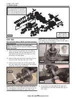
15” Idler Wheel
(SR-80)
Note:
The 15” idler and 10” bogie wheels may be
removed from the SR-70 and SR-80 undercarriages
without removing the tracks.
Removal
1.
Raise and support the machine by following the
jacking procedure on page 4-2.
2.
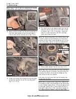
Break up and remove any foreign material from the
cavity between the suspension rail and the drive
table support. (fig. 13-1)
Note:
A shop vac or pressure washer will work well to
remove material from this cavity.
13. Undercarriage
13-1
!WARNING!
!WARNING!
Required Tools
Socket/impact wrench
Heavy duty hydraulic jack
Combination wrench
ASV approved jack stands (2)
Shop vac or Pressure washer
13-1
Cavity
https://tractormanualz.com/
Summary of Contents for ASV SR70
Page 5: ...IV https tractormanualz com...
Page 11: ...1 6 https tractormanualz com...
Page 41: ...4 20 https tractormanualz com...
Page 87: ...12 8 https tractormanualz com...
Page 105: ...14 6 https tractormanualz com...
Page 109: ...15 4 https tractormanualz com...
Page 125: ...16 16 https tractormanualz com...
Page 133: ...17 8 https tractormanualz com...
Page 137: ...18 4 https tractormanualz com...
Page 139: ...19 2 https tractormanualz com...

