background image

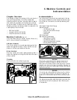
Chapter Overview

This chapter contains an overview of the machine con-
trols and instrumentation. For further information
regarding machine controls, instrumentation or opera-
tion, refer to the operation and maintenance manual
for the SR-70/80. Included here are illustrations of the
following controls and instrumentation components and
a description of their functions.

• 

Machine Controls

• 

Guage Location and Function

• 

Switch Location and Function

Machine Controls 

(fig. 5-1)

There are three primary machine controls: lift arm con-
trol (1), drive control (2) and throttle (3).

Lift Arm Control

The lift arm control (1) is a pilot operated joystick that
allows the operator to raise or lower the lift arms and
dump or curl the quick attach mechanism.

Drive Control

The drive control (2) is also a pilot operated joystick. It
allows the operator to change the direction and speed
of the machine.

Throttle

The foot throttle (3) controls engine rpm.

Instrumentation

The Instruments (Figure 5-2) are positioned in the lap
bar for good visibility and when seated inside the oper-
ator enclosure. Instruments include the following com-
ponents.

(1)

Engine Temperature Gauge

(2) 

Multi-Gauge 

• Oil Pressure Gauge
• Hyd. Oil Temperature Gauge
• Fuel Gauge
• Voltmeter

(3)

Tachometer

(4)

Indicator Light Display

• High Range Indicator
• Low Range Indicator
• Glow Plug Operation Indicator
• Parking Brake Indicator

NOTICE

If the engine coolant temperature, engine oil pressure or
hydraulic oil temperature gauges read above normal (or
below normal for engine oil pressure) during normal machine
operation, shut the machine down immediately. Diagnose the
problem and make any necessaryrepairs before continuing to
operate the machine.

NOTICE

If the battery low-voltage light illuminates, drive the machine
to a suitable location and shut the engine off. Diagnose the
problem and make needed repairs before continuing to oper-
ate.

The glow plug operation light illuminates only when the
key switch is turned to engine pre-heat, showing nor-
mal operation.

5. Machine Controls and

Instrumentation

5-1

2

3

1

2

5-1

5-2

1

3

4

https://tractormanualz.com/

Summary of Contents for ASV SR70

Page 1: ...nglish All Language Geographic Region Serial Number Range This manual is complements of TrackLoaderParts com The world s best source for ASV parts Track Loader Parts 6543 Chupp Road Atlanta Georgia 30...

Page 2: ...2 2 Service Tools 2 2 3 Circuit Diagrams Chapter Overview 3 1 Hydraulic Charge Circuit 3 1 Hydraulic Auxiliary Circuit 3 2 Hydraulic Drive Circuit 3 3 Lift Arm Control Valve 3 4 Hydraulic Pilot Gener...

Page 3: ...dure 7 6 8 Radiator and Oil Cooler Chapter Overview 8 1 Personal Safety 8 1 Machine Preparation 8 1 Removal Installation 8 1 Fan Guard 8 1 Removal Procedure 8 1 Installation Procedure 8 2 Fan Shroud 8...

Page 4: ...15 3 16 Hydraulic Component Service Chapter Overview 16 1 Personal Safety 16 1 Disassembly Assembly 16 1 Hydraulic Cylinder 16 1 Disassembly Procedure 16 1 Assembly Procedure 16 3 Lift Arm Control Va...

Page 5: ...IV https tractormanualz com...

Page 6: ...Track Loader may be unfamiliar with many of the systems on the machine This makes it especially important to use caution when performing service tasks Familiarize yourself with the affected system s a...

Page 7: ...amounts of water for at least 15 minutes Call Physician Keep out of reach of children Batteries Do not smoke when inspecting the battery electrolyte level Never disconnect any charging unit circuit or...

Page 8: ...sibly overspeed and cause bodily injury death or property damage Be prepared to shut off the fuel and air supply to the engine in order to stop the engine 9 Be careful when removing cover plates Gradu...

Page 9: ...iency particulate air filter HEPA filter can also be used 2 Use exhaust ventilation on permanent machining jobs 3 Wear an approved respirator if there is no other way to control the dust 4 Comply with...

Page 10: ...ese areas as often as necessary to avoid combustion Failure to do so could result in fire that may cause machine damage personal injury or even death 2 Speed if equipped To engage Press the button loc...

Page 11: ...1 6 https tractormanualz com...

Page 12: ...introduced from the quick couplers Lift Arm Control Valve Make Rexroth Type Load Sense Oil Cooler Operating pressure 150 psi 1034 kPa Bypass relief pressure 80 psi 689 kPa Hot oil sending unit 225 F...

Page 13: ...introduced from the quick couplers Lift Arm Control Valve Make Rexroth Type Load Sense Oil Cooler Operating pressure 150 psi 1034 kPa Bypass relief pressure 80 psi 689 kPa Hot oil sending unit 225 F...

Page 14: ...t also contains hose routing information for the control configurations for the drive and lift arm pilot controls Figure 3 1 SR 70 80 Hydraulic Charge Circuit Hydraulic Charge Circuit 3 Circuit Diagra...

Page 15: ...ircuit Diagrams OIL COOLER TO TANK TO ATTACHMENT CASE DRAIN Q C LOAD SENSE TO LIFT ARM CYL TO AUXILIARY Q C TO TANK FLOW AUXILIARY PUMP LOADER CONTROL LIFT ARM VALVE PILOT GEN BLOCK TO LIFT ARM CYL TO...

Page 16: ...70 80 Hydraulic Drive Circuit 3 3 Rubber Track Loader 3 Circuit Diagrams DRIVE MOTOR DRIVE MOTOR DRIVE PUMP DRIVE CONTROL TO COOLER TANK CASE DRAIN BRAKE 2 SPEED SHIFT SR 80 DRIVE PRESSURE RELIEF VALV...

Page 17: ...Figure 3 4 SR 70 80 Lift Arm Control Valve 3 4 Rubber Track Loader 3 Circuit Diagrams RELIEF VALVE SETTINGS B3 3307 PSI B2 3147 PSI B1 3640 PSI A3 3307 PSI A2 3669 PSI A1 Anti Cavitation Check Valve h...

Page 18: ...Hydraulic Pilot Generation Block Figure 3 5 SR 70 80 Hyd Pilot Generation Block 3 5 Rubber Track Loader 3 Circuit Diagrams https tractormanualz com...

Page 19: ...Electrical Attachment Outlet Figure 3 6 SR 70 80 Electrical Attachment Outlet 3 6 Rubber Track Loader 3 Circuit Diagrams https tractormanualz com...

Page 20: ...Drive Control line routing Figure 3 7 SR 70 80 Standard Drive Control 3 7 Rubber Track Loader 3 Circuit Diagrams https tractormanualz com...

Page 21: ...Lift Arm Control line routing Figure 3 8 SR 70 80 Lift Arm Control 3 8 Rubber Track Loader 3 Circuit Diagrams https tractormanualz com...

Page 22: ...The lift arm brace is used to support the weight of the lift arms much like jack stands are used to mechanically support vehicle weight To install the lift arm brace 1 Park the machine on level groun...

Page 23: ...erform maintenance Exercise caution when jacking the machine Always use a jack that is capable of lifting the machine and support its weight with ASV approved jack stands while suspend ed Never work o...

Page 24: ...eaned from the undercar riages more often to minimize component wear A pressure washer works well for cleaning materials from the undercarriages At times when a pressure washer is not available use a...

Page 25: ...orward 5 feet to remove belt slack from the lower and rearward portions of the track 2 Lay a straight edge along the top of the track bridging the drive sprocket and front idler wheel 3 Apply 90 lbs o...

Page 26: ...aring assembly J from the shaft 6 Remove the sprocket mounting bolts C then remove the sprocket Note You may need to pry or lift the track upwards with a hoist above the drive sprocket to provide clea...

Page 27: ...removal procedure is identical with this exception fig 4 11 Track Removal 1 Break up and remove any foreign material from the cavity between the suspension rail and the drive table support fig 4 12 N...

Page 28: ...e the wheel SR 80 only fig 4 18 4 19 8 Use a pry bar to peel the track over the inner wheel s toward the outside of the machine fig 4 20 9 Once the track is off of the front wheel s pull the rear of t...

Page 29: ...y and in position to slide over the inner idler wheel s at the front fig 4 27 6 Pull all of the slack forward and make sure the track drive lugs are properly meshed with the sprocket to provide as muc...

Page 30: ...u torque the mounting bolts to spec fig 4 31 10 Install the scraper onto the suspension rail and tighten the bolts to secure it in place SR 80 only fig 4 32 11 Install the outer idler wheel and secure...

Page 31: ...he cover then remove the cover The primary element B should be exposed 5 Remove the primary element and inspect it If it appears damaged in any way replace it If the ele ment is heavily soiled replace...

Page 32: ...eavy duty air filter manufactur ers will not warrant the air filter once it has been cleaned Fuel Filter The fuel filter removes contaminants from the fuel as it enters the engine for combustion Over...

Page 33: ...nce from the bottom of the straight edge to the top surface of each belt deflection Fan belt deflection should meas ure 3 8 7 16 A C if properly tensioned 5 If the belts are loose or tight adjust tens...

Page 34: ...procedure 2 Perform the belt tension check and adjustment procedures on page 4 12 to complete the installation A C Belt Removal Installation To remove the A C belt 1 Follow steps 1 and 2 of the belt...

Page 35: ...e the correct size combi nation socket wrench to keep the drain plug in reusable condition fig 4 48 5 Remove the engine oil filter by hand or with strap if necessary fig 4 49 6 Once the filter has bee...

Page 36: ...W 30 Heavy Duty Engine Oil for most conditions In the event of an alternate working environment the following chart may be used as a guide to oil viscosity grades You may also use a quality engine oil...

Page 37: ...ic oil onto the filter gasket surface and then threading them onto their respective filter heads Tighten filters by hand as instructed by the label located on the filter or filter box 8 Install the hy...

Page 38: ...Make sure the engine is off and cool 2 Using compressed air or a pressure washer thor oughly clean radiator oil cooler as shown Note Make sure water nozzle is at least 12 8 for air from the cooler an...

Page 39: ...ind the access cover on the lower right side of the cab interior fig 4 63 In the event of an electrical malfunction the most logi cal place to start is at the fuse panel Check the fuse related to the...

Page 40: ...ily Clean often as necessary Undercarriages Inspect Daily Clean often as necessary Engine compartment Inspect Daily Clean often as necessary Drive sprocket rollers Inspect 50 hr Replace if damaged or...

Page 41: ...4 20 https tractormanualz com...

Page 42: ...n The Instruments Figure 5 2 are positioned in the lap bar for good visibility and when seated inside the oper ator enclosure Instruments include the following com ponents 1 Engine Temperature Gauge 2...

Page 43: ...tional switches are listed below 1 Ignition 2 Hour Meter 3 Beacon optional 4 Wiper optional 5 Heater Fan optional 6 Parking Brake 7 Headlight 8 Bucket Pos 9 Hight Flow Aux 10 Low Flow Aux 11 Hyd Q A 5...

Page 44: ...terminals tape the battery clamps and remove the key from the ignition switch prior to performing any service work on a Rubber Track Loader Place a Do Not Operate tag prominently on the ma chine to in...

Page 45: ...h fig 6 5 4 Pivot the panel further backward to expose the connectors on the lower switches and disconnect them You may then remove the panel fig 6 6 6 7 Note The connectors on the harness are labeled...

Page 46: ...in the disassembly procedure the gauges may be replaced if necessary 3 If gauges must be removed remove the nuts securing the backing plate to the gauge fig 6 12 4 The gauge may now be removed for re...

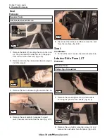
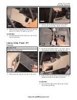
Page 47: ...seat fig 6 17 5 Disconnect the harness and then remove the seat from the machine fig 6 18 Seat Installation 1 To install the seat reverse the removal procedure Interior Side Panel LT Removal 1 Remove...

Page 48: ...access cover fig 6 22 2 Remove the mounting screws 6 and washers securing the panel to the chassis fig 6 23 3 Disconnect the ignition switch hour meter and any other switches from the cab harness fig...

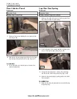
Page 49: ...he cab to access the gas spring 2 Put the lap bar in the raised position to relieve ten sion on the lap bar gas spring fig 6 28 3 Using a small screwdriver remove the retaining clip from each end of t...

Page 50: ...ion switch prior to performing any service work on a Rubber Track Loader Place a Do Not Operate tag prominently on the ma chine to inform personnel that the machine is being worked on Removal and Inst...

Page 51: ...d on page 4 1 of this manual 2 Tilt and support the operator enclosure cab as described on page 4 2 of this manual optional 3 Loosen the hose clamps securing the vent hoses to the left rear tank end f...

Page 52: ...nd mandates 8 Remove the bolts securing the fuel tank to the fenders fig 7 10 9 Remove the bolts 3 securing the fuel tank to the front mounting plate fig 7 11 10 Now that the tank is loose and empty l...

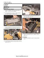
Page 53: ...er fig 7 14 4 Pry the throttle cable off of the ball stud on the foot pedal fig 7 15 5 Remove the bolts 4 securing the footwell assem bly to the chassis fig 7 16 6 Remove the footwell from the chassis...

Page 54: ...roper operation when re installed 3 Remove the foot throttle from the machine Installation 1 To install the foot throttle assembly reverse the removal procedure Hood Assembly Removal 1 Remove the bolt...

Page 55: ...hood assembly from the machine fig 7 23 4 Carefully set the hood assembly aside fig 7 24 Installation 1 To install the hood assembly reverse the removal procedure 7 6 Rubber Track Loader 7 Chassis Fu...

Page 56: ...ey from the ignition switch prior to performing any service work on a Rubber Track Loader Place a Do Not Operate tag prominently on the ma chine to inform personnel that the machine is being worked on...

Page 57: ...olts 2 securing the fuel pump filter assembly to the radiator support and lay it aside over the bumper to allow clearance to remove the shroud and fan fig 8 5 2 Remove the bolts 6 securing the radiato...

Page 58: ...conditioner contains alkali Avoid con tact with skin and eyes NOTICE Collect and contain liquids in suitable containers Dispose of all liquids according to local regulations and mandates 1 Perform th...

Page 59: ...ug the line and cooler opening upon disassembly fig 8 15 7 Loosen the clamps securing the upper and lower coolant hoses to the radiator then disconnect the hoses from the radiator fig 8 16 8 17 8 Tilt...

Page 60: ...erforming any type of service work on a Rubber Track Loader read and understand Chapter 1 Product Safety for personal safety information Removal and Installation Removal and installation procedures ar...

Page 61: ...ect the hoses and lines attached to the two upright portions of the tank fig 9 1 9 2 9 3 6 Remove the clamps securing the quick attach hard lines and the test port line that run from the pilot generat...

Page 62: ...ent Remove all line clamps fig 9 8 11 Disconnect the lift cylinder hoses from the hard lines to allow the bucket cylinder lines to be removed fig 9 9 12 Disconnect the bucket cylinder hard lines from...

Page 63: ...hine fig 9 14 9 15 16 Remove the clamps securing the auxiliary hydraulic lines to the chassis fig 9 16 17 Disconnect the auxiliary hydraulic lines from the lift arm control valve and the hoses leading...

Page 64: ...emoved 20 Remove the auxiliary hydraulic tubes from the machine 21 Disconnect the lower portions of the cab support gas springs from the chassis fig 9 23 22 Label then disconnect any control hoses com...

Page 65: ...26 Remove the bolts securing the metal tank restraint straps them remove them from the machine fig 9 28 27 Slide the quick attach and test port tubes forward so that they do not interfere with the re...

Page 66: ...nce the tank is over the axle mounts lift and remove it from the chassis as shown fig 9 32 9 33 9 34 Installation 1 To install the hydraulic reservoir reverse the removal procedure Note The only servi...

Page 67: ...6 and 9 37 5 The suction screen is now accessible for inspec tion or replacement Note If removal is necessary thread the suction screen off of the flange weldment and remove Installation 1 To install...

Page 68: ...nderstand Chapter 1 Product Safety for personal safety information Removal and Installation Removal and installation procedures are provided for the following lift arm drive control components Pilot C...

Page 69: ...gnet is now exposed as well as the mounting bolts securing the joystick to the bracket figure 10 2 5 Label each of the hoses during the removal process to aid in reassembly 6 Remove the bolts 3 securi...

Page 70: ...and 11 of the lift arm joystick control removal process 2 Remove the allen bolt from the underside of the magnet fig 10 10 3 Disconnect the magnet harness connector from the machine 4 Lift the joysti...

Page 71: ...onal clear ance for line removal fig 10 13 10 14 5 Disconnect all lines and hoses from the valve to allow for removal figure 10 15 10 16 6 Remove the carriage bolts 3 securing the loader valve to the...

Page 72: ...d and understand Chapter 1 Product Safety for personal safety information The hydraulic system fluid should be changed follow ing any hydraulic component service according to the procedure described o...

Page 73: ...7 Remove the upper and lower 12 point bolts secur ing the charge pump to the engine fig 11 2 8 Remove the charge pump from the engine fig 11 3 Installation 1 To install the charge pump reverse the rem...

Page 74: ...he right side of the pump then disconnect it fig 11 6 5 Loosen the clamps securing the hoses to the inlet weldment attached to the bottom of the pump fig 11 7 6 Loosen and remove the split flange clam...

Page 75: ...rvice on the cooling or hydraulic systems NOTICE Collect and contain liquids in a suitable container Dispose of all fluids according to local regulations and mandates During disassembly plug and cap h...

Page 76: ...bolts in position 11 13 To Oil Cooler return To Drive Motor LT To Drive Motor RT From Charge Filter BTM BTM BTM BTM TOP BTM Top Bottom Drive Pump Hoses View is from the top The pump is to be perceive...

Page 77: ...bearing assembly fig 11 20 4 Remove the bearing support plate from the under carriage fig 11 21 5 Use a hammer to tap around the circumference of the bearing cap which releases the outward pres sure h...

Page 78: ...ve motor to the drive table fig 11 28 12 Lift the drive motor straight upward until it clears the drive table then forward to expose the hydraulic hoses for removal fig 11 29 Note There are two large...

Page 79: ...1 31 Installation 1 To install the drive motor into the undercarriage reverse the removal procedure Note During the removal of the bearing cap the bulged or domed area is beaten inward When rein stall...

Page 80: ...g any type of service work on a Rubber Track Loader read and understand Chapter 1 Product Safety for personal safety information Removal and Installation Removal and installation procedures are provid...

Page 81: ...ry hot at operating tem perature Make sure the machine is off and cool before attempting to service the exhaust system 1 Perform the radiator oil cooler removal procedure on page 8 3 to provide access...

Page 82: ...the inlet pipe from the muffler It may be necessary to use levers to force the inlet pipe sec tion out of the muffler fig 12 11 Note Use caution not to damage the pipe or connec tion point during rem...

Page 83: ...1 Remove the cover and the filter elements from the air cleaner assembly fig 12 15 2 Loosen the clamp securing the intake hose to the air cleaner housing fig 12 16 3 Remove the bolts and nuts securing...

Page 84: ...3 Raise and support the operator enclosure cab as described on page 4 2 of this manual 4 Perform steps 2 7 of the exhaust removal proce dure on page 12 2 of this manual 5 Remove the center belly pan...

Page 85: ...t hand portion of the engine compart ment when viewed from the rear fig 12 23 11 Disconnect the case drain filter and bracket from the engine adapter plate and lay it aside It is situ ated beneath the...

Page 86: ...ig 12 30 or the rear window could be damaged fig 12 31 18 Slide the engine rearward to clear the forward motor mounts then up and out between the radia tor supports fig 12 32 Installation 1 To install...

Page 87: ...12 8 https tractormanualz com...

Page 88: ...ntly on the ma chine to inform personnel that the machine is being worked on Prior to performing any type of service work on a Rubber Track Loader read and understand Chapter 1 Product Safety for pers...

Page 89: ...Remove the outer scraper plate from the suspen sion rail fig 13 6 8 Remove the bolts securing the inner wheel to the hub then remove the wheel fig 13 7 13 8 9 Repeat this procedure as necessary to re...

Page 90: ...on 1 To install the idler wheels on the SR 70 reverse the removal procedure Torque the 15 wheel mounting bolts upon installation to 90 10 Lb Ft Torque the 10 wheel mounting bolts upon installation to...

Page 91: ...During wheel removal replacement it is nec essary to remove inspect and clean all components prior to reassembly to ensure proper function 5 Remove both wheels from the hub fig 13 17 Note Take care n...

Page 92: ...he axle and far side bearing out of the hub as shown fig 13 20 13 21 7 If it is necessary to remove the other bearing for replacement press it out as well If not you may leave this bearing in the hub...

Page 93: ...3 25 13 Once the seals are in place wipe the mating sur faces of the face seals with a clean shop cloth and alcohol in a circular motion ending in a gentle sweep from the inside to the outside of the...

Page 94: ...LubeTM 10W 30 Heavy Duty Engine Oil Then rein stall the plug fig 13 33 13 34 22 Repeat this procedure on the other half of the bogie assembly if necessary prior to installing the two halves back onto...

Page 95: ...te If you are removing the outer or rear hub assemblies you will be able to remove the hub assem bly once step three is complete 4 Using a press and tool 0403 336 press the bearing sleeve out of the h...

Page 96: ...with tools 0403 337 and 0403 333 fig 13 43 8 Press the bearing sleeve out of the rear bearing using tool 0403 336 fig 13 44 9 Remove the face seals and retaining ring from the bearing sleeve for clean...

Page 97: ...dry to ensure a good seal when assembled 12 Once components are clean and dry install half of the rear face seal into the bearing sleeve Make sure to work the rubber seal down into place within the se...

Page 98: ...hub with tool 0403 336 until seated fig 13 54 19 Flip the hub over support the bearing sleeve from the bottom with tool 0403 335 and set it onto the press for center seal installation fig 13 55 20 Ins...

Page 99: ...he center portion of the hub fig 13 61 27 Add 2 oz 1 oz SR 70 of Posi Lube 10W 30 Heavy Duty Engine Oil to the hub as shown then reinstall the plug and tighten fig 13 62 28 The hub assembly is now rea...

Page 100: ...ead and understand Chapter 1 Product Safety for personal safety information The hydraulic system fluid should be changed follow ing any hydraulic component service according to the procedure described...

Page 101: ...ittings to prevent fluid loss and or sys tem contamination fig 14 3 4 Remove the bolts securing the front and rear lift arm cylinder pivot pins to the lift arm and lift arm tower fig 14 4 5 Remove the...

Page 102: ...ucket Tilt Cylinder Removal 1 Raise the lift arms and support them with the lift arm brace as described on page 4 1 fig 14 8 2 Place a suitable catch container beneath the cylin der fittings then disc...

Page 103: ...d fig 14 13 8 Use a pry bar to pry the lower cylinder eyelet out of the upper Q A mount as shown fig 14 14 9 Use a hammer and a brass punch to tap the upper pin most of the way out of the lift arm wel...

Page 104: ...hine off and cool and with all hydraulic actuators relaxed loosen the pressure release valve on the top of the auxiliary quick cou pler block fig 14 18 2 Once loose remove the valve from the block by...

Page 105: ...14 6 https tractormanualz com...

Page 106: ...prominently on the ma chine to inform personnel that the machine is being worked on Prior to performing any type of service work on a Rubber Track Loader read and understand Chapter 1 Product Safety...

Page 107: ...n assembly out of the quick attach fig 15 6 Note At this time the locking pin assembly compo nents are easily accessible for replacement Inspect them for visible wear or damage and replace them as nec...

Page 108: ...vot pins that connect the quick attach to the lift arm and cylinders All four pins are removed in a similar manner Installation 1 To install the quick attach pivot pins reverse the removal procedure 2...

Page 109: ...15 4 https tractormanualz com...

Page 110: ...c component service according to the procedure described on page 4 16 Disassembly Assembly Disassembly and assembly procedures are provided for the following components Hydraulic Cylinders Lift Arm Co...

Page 111: ...impaired func tion Defective components must be repaired or replaced 7 With the piston and rod removed from the cylinder inspect the cylinder bore for scratches or other damage If any are present tha...

Page 112: ...d gland outer seal from the end gland figure 16 10 16 Thoroughly clean all parts to prevent contamina tion of hydraulic oil when reinstalled Assembly 1 Install new seals and components in place of the...

Page 113: ...on and inspect the seals for damage replace if necessary figure 16 15 5 Remove the inlet port assemblies and inspect the seals for damage replace if necessary figure 16 16 16 17 6 Once the inlet port...

Page 114: ...l in place in a vice without damaging the spool and remove the end cap with an allen wrench fig 16 21 8 Remove the spring from the spool fig 16 22 9 Remove the load check spool with a low profile need...

Page 115: ...axed remove the drive motor from the undercarriage by following the procedure in sec tion 13 2 Remove all but four of the allen bolts on opposite sides of the cover holding the rear cover onto the dri...

Page 116: ...8 Remove the piston from the motor Inspect the seal for any damage fig 16 29 9 Inspect the seal for any damage fig 16 30 10 Remove the allen bolts securing the upper casting to the drive motor fig 16...

Page 117: ...ion that may affect operation fig 16 36 4 Inspect the surfaces of the cam ring and the piston rollers for imperfections Any damage found indi cates a need for component replacement fig 16 37 5 Using a...

Page 118: ...parts then reassemble the motor by reversing the disassembly procedure Drive Pump Drive Relief Valves Disassembly Adjustment 1 With machine off and cool and with hydraulic actu ators relaxed remove th...

Page 119: ...osi power relief valve adjustment pro cedure in section 17 of this manual 1 Remove the valve from the drive pump as shown in figure 16 46 Installation 1 To install reverse the removal procedure Drive...

Page 120: ...embly then inspect 5 Remove the swash plate along with the bearings and inspect them for any damage or scratching that could affect operation fig 16 52 16 53 6 Remove the snap ring holding the shaft s...

Page 121: ...ated fig 16 56 2 Replace the seal with a new one and install taking care not to damage it upon installation fig 16 57 3 Install the snap ring that secures the shaft bear ing and seal in place fig 16 5...

Page 122: ...pivots are installed check to make sure both of them are properly mated with the pins Using a blade type screwdriver turn the pivots slightly to the right or left The swash plate should move with the...

Page 123: ...fig 16 66 5 Lift the cover off to expose the pump components and the o ring seal Inspect the o ring for damage replace if necessary fig 16 67 6 Inspect the valve plate face both sides for scratches o...

Page 124: ...ipper faces for scratches or any other dam age that can be felt with a fingernail fig 16 70 Assembly 1 To reassemble reverse the disassembly proce dure 16 15 Rubber Track Loader 16 Hydraulic Component...

Page 125: ...16 16 https tractormanualz com...

Page 126: ...e to be expected but If there is significant metallic debris found in either filter certain components of your hydraulic system may be contaminated To inspect for contamination label the hydraulic fil...

Page 127: ...If necessary adjust the charge relief pressure To adjust a Tilt the cab as described on page 4 2 of this manual to access the pump b Locate the charge relief valve on the top of the drive pump fig 17...

Page 128: ...the low or high flow auxiliary hydraulics with no auxiliary attachment fastened to the quick couplers This action will send oil over relief and you will read the actual pressures required to acti vate...

Page 129: ...this process are clean and free of contaminants that may potentially cause damage to the hydraulic pump and or system components Drive pressure is used to turn the drive motors that power your tracks...

Page 130: ...y related to engine rpm and adjusts drive pump flow to maximize torque and prevent engine stall during high load conditions This procedure should only be performed if you suspect that the Posi Power r...

Page 131: ...ts If an auxiliary flow prob lem is suspected the following procedures should be performed Note If an auxiliary circuit problem is suspected per form all pressure test and adjustment procedures as nec...

Page 132: ...Turn the adjustment screw on the pilot generation block pressure reducing valve clockwise to increase the flow within the low flow circuit until correct see page 3 5 view D item 5 to locate Problem 5...

Page 133: ...17 8 https tractormanualz com...

Page 134: ...condition Hoses no visible sign of wear Fittings no apparent leaks Battery cables Fuse panel fuses in place and operational Controls for neutral A simple visual inspection and operational check can i...

Page 135: ...trol solenoid 3 Drive control joystick pilot control malfunction 4 Low charge pressure 5 Parking brake switch in on position 6 Faulty parking brake switch Problem 5 Tracks are operational but lift arm...

Page 136: ...ther or not the problem lies with the machine itself or with the engine A machine problem should be repaired by an ASV dealer while an engine specific problem should only be repaired by a representati...

Page 137: ...18 4 https tractormanualz com...

Page 138: ...40 6 gallons Engine Anti freeze Coolant ASV Posi Lube Long Life 50 50 Antifreeze Coolant Capacity 3 125 U S gallons P N 0300 766 1 gallon P N 0402 841 6 gallons Hydraulic Oil ASV Posi Lube Premium All...

Page 139: ...19 2 https tractormanualz com...

Page 140: ...b ft 1 2 75 15 lb ft 9 16 120 22 lb ft 5 8 160 30 lb ft 3 4 275 37 lb ft 7 8 460 60 lb ft 1 660 75 lb ft 1 1 8 960 110 lb ft 1 1 4 1320 150 lb ft 1 3 8 1780 220 lb ft 1 1 2 2280 260 lb ft Thread Size...

Page 141: ...Terex Construction Americas 8800 Rostin Road Southaven MS 38671 888 201 6008 662 393 1800 www terex com https tractormanualz com...

Reviews: