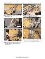
23.
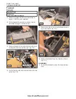
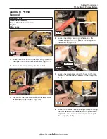
Remove the lower hose restraints to allow the
hoses to be pulled through the chassis. (fig. 9-25)
24.
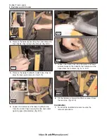
Pull the hoses up through the chassis opening and
lay them aside as shown (both sides). (fig. 9-26)
25.
Disconnect the wiring running through the hose
passageway and pull it through the opening as
shown. (fig. 9-27)
26.
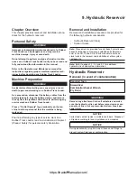
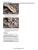
Remove the bolts securing the metal tank restraint
straps, them remove them from the machine.
(fig. 9-28)
27.
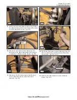
Slide the quick attach and test port tubes forward
so that they do not interfere with the reservoir
(tank) moving upwards in the chassis. (fig. 9-29)
28.
Slide the various control hoses to the side of the
reservoir (tank) so that they do not interfere with
the tank moving upwards in the chassis. (fig. 9-30)
9-6
Rubber Track Loader
9. Hydraulic Reservoir
9-26
9-25
9-27
9-28
9-29
9-30
https://tractormanualz.com/
Summary of Contents for ASV SR70
Page 5: ...IV https tractormanualz com...
Page 11: ...1 6 https tractormanualz com...
Page 41: ...4 20 https tractormanualz com...
Page 87: ...12 8 https tractormanualz com...
Page 105: ...14 6 https tractormanualz com...
Page 109: ...15 4 https tractormanualz com...
Page 125: ...16 16 https tractormanualz com...
Page 133: ...17 8 https tractormanualz com...
Page 137: ...18 4 https tractormanualz com...
Page 139: ...19 2 https tractormanualz com...


