MAINTENANCE
3-30
275 SERIES II MM190 (NIL)
2. Park on a level surface, stop the engine, and
set the machine parking brake.
FOR SAFETY: Before leaving or servicing
machine; stop on level surface, set parking brake,
and turn off machine.
3. Check the governor belt tension as described
in
GOVERNOR BELT
.
4. Place the throttle lever in the “normal” or (Fast
1) position. There should be a 0.03 to 0.06 in (1
to 2 mm) space between the carburetor lever
and the lever stop. Adjust the throttle rod as
required.
5. Move the throttle lever to the (Idle) position.
Start the engine and adjust the engine idle
speed screw so the engine operates at 950 +
50 rpm.
6. Place the throttle lever in the “litter” or
(Fast 2) position. Turn the side brush and main
brushes on, and adjust the high speed stop
screw so the engine operates at 2600 rpm.
Then adjust the surge screw so the engine
operates at 2650 rpm. Tighten all lock nuts.
FOR SAFETY: Before leaving or servicing
machine; stop on level surface, set parking brake,
and turn off machine.
7. Place the throttle lever in the “normal” or (Fast
1) position. Adjust the low speed stop screw so
the engine operates at 2200 +
50 rpm.
8. Stop the engine.
9. Check and adjust the throttle cable position
and the throttle lever stops to allow full linkage
movement.
GOVERNOR -- GASOLINE, LPG (For machines
serial number 006500 and above)
The electronic governor controls engine speed. The
governor consists of an ignition control assembly
and control box located in front of the engine air
cleaner,and an actuator mounted on the engine. The
ignition control box regulates the actuator, which in
turn controls the throttle.
The electronic governor is factory set and is not user
serviceable.
IGNITION SYSTEM -- GASOLINE, LPG
SPARK PLUGS
Clean or replace and adjust spark plugs after every
400 hours of operation. Spark plug gaps are best
checked with a wire gauge unless the plug is
dressed to obtain a correct reading with a flat gauge.
The adjustment should always be made on the side
electrode and never on the center electrode, which
may cause a broken porcelain.
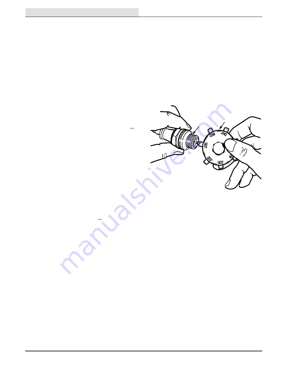
“Gapping” the electrode tip is more easily done with
the proper tools.
A
B
01471
GAPPING SPARK PLUG
A. Spark Plug
B. Gapping Tool
The proper spark plug gap is 0.035 in (0.9 mm) for
machines below serial number 006500. The proper
spark plug gap is 0.039 in (1 mm) for machines
serial number 006500 and above.
Spark plugs must be correctly installed in order to
obtain good performance. It is a simple but
important matter to follow these procedures when
installing plugs:
1. Clean the spark plug seat in the cylinder head.
2. Use a new seat gasket and screw the plug in
by hand.
3. Tighten the spark plugs to 22 to 28 ft lb
(30 to 38 Nm) with a socket wrench of the
correct size.
Summary of Contents for 275 Series II
Page 1: ...r 275 Series II Sweeper Scrubber ...
Page 6: ...ABOUT THIS MANUAL 275 SERIES II MM190 12 89 d ...
Page 18: ...SPECIFICATIONS 1 2 275 SERIES II MM190 12 89 ...
Page 22: ...SPECIFICATIONS 1 6 275 SERIES II MM190 12 89 ...
Page 24: ...OPERATION 275 SERIES II MM190 12 89 2 2 ...
Page 74: ...MAINTENANCE 3 14 275 SERIES II MM190 12 89 04644 HYDRAULIC SCHEMATIC LOW DUMP MODEL ...
Page 75: ...MAINTENANCE 3 15 275 SERIES II MM190 12 89 04645 HYDRAULIC SCHEMATIC MULTI LEVEL DUMP MODEL ...
Page 97: ...MAINTENANCE 3 37 275 SERIES II MM190 12 89 04643 ELECTRICAL SCHEMATIC DIESEL ...
Page 98: ...MAINTENANCE 3 38 275 SERIES II MM190 12 89 04642 ELECTRICAL SCHEMATIC ACCESSORIES ...
Page 99: ...MAINTENANCE 3 39 275 SERIES II MM190 6 90 06187 ELECTRICAL SCHEMATIC AUTO SHAKER RFS ...
Page 100: ...MAINTENANCE 3 40 275 SERIES II MM190 6 90 06187 ELECTRICAL SCHEMATIC AUTO SHAKER RFS ...


