MAINTENANCE
3Ć9
1186 MM267 (6–94)
7. Squeeze it dry in a cloth.
8. Remove the dry cartridge-type filter nut and
cup.
9. Gently remove the dry cartridge-type air
filter.
10. Clean or discard the dry cartridge-type air
filter.
11. Clean the interior of the air cleaner housing
with a damp cloth. Clean the element
sealing surfaces.
12. Position the cleaned or new, dry
cartridge-type air filter on the engine.
13. Slide the air filter cup over the air filter stud.
14. Thread and tighten the nut on the air filter
stud.
15. Oil the foam pre-cleaner with 1 oz (30 cc) of
clean engine oil. Squeeze the pre-cleaner to
distribute the oil evenly throughout the foam.
16. Slide the foam pre-cleaner over the dry
cartridge-type filter.
17. Position the air filter cover over the air filter
assembly. Tighten the wing nut on the air
filter stud.
FUEL SYSTEM – GASOLINE
FUEL FILTER
The fuel filter traps fuel impurities. It is located
below the air filter. Replace the filter when
diminished fuel flow indicates a dirty filter.
CARBURETOR
The carburetor needs no regular maintenance. It
is set so there is no idle speed––only the normal
operating speed. The initial setting of the idle and
main fuel needle valves is made by turning them
all the way in. Turn the idle fuel adjusting needle
counterclockwise to a minimum of one and
one-quarter turns to a maximum of one and
one-half turns. Turn the main fuel adjusting needle
out counterclockwise to a minimum of one and
three-quarters turns to a maximum of two turns
open. Final adjustment is made with the engine
running and warm.
The carburetor should be adjusted with the fuel
tank approximately one-half full and with the
engine running at approximately 800 RPM. Turn
the main fuel adjusting needle valve out until the
engine begins to lose speed (rich). Note the
position of the needle. Then turn the needle in.
The engine speed may increase, then it will
decrease as the needle is turned in (lean). Note
the position of the needle. Set the needle half way
between the rich and lean positions.
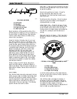
A
B
03075
CARBURETOR ADJUSTMENTS
A. Idle Needle Valve
B. Main Fuel Needle Valve
FUEL SYSTEM – LPG
LPG FUEL SYSTEM
The vapor withdrawal LPG fuel system is made
up of four components which are: the LPG fuel
tank, fuel filter lock, the regulator, and the
carburetor.
LPG fuel flows from the LPG tank, under its own
pressure, to the fuel filter lock. The fuel filter lock
filters unwanted tank scale and deposits out of the
LPG fuel. The fuel filter lock also stops the flow of
LPG fuel when the engine is not operating. The
LPG module controls the fuel filter lock. When the
charging system produces sufficient energy, it
permits an electrical current to open the fuel filter
lock which allows LPG fuel to flow on to the
regulator.
The regulator reduces the pressure of the LPG
fuel to the level required by the carburetor. From
the regulator, the LPG fuel is sent to the
carburetor where it is finally metered into the
combustion chamber air flow.
Summary of Contents for 1186
Page 1: ...1186 MM267 Rev 05 12 95 Operator Manual ...
Page 8: ...GENERAL INFORMATION 1186 MM267 6 94 vi ...
Page 10: ...SPECIFICATIONS 1186 MM267 6 94 1Ć2 ...
Page 14: ...OPERATION 1186 MM267 6 94 2Ć2 ...
Page 32: ...MAINTENANCE 1186 MM267 6 94 3Ć2 ...
Page 46: ...MAINTENANCE 1186 MM267 6 94 3Ć16 ELECTRICAL SCHEMATIC 06779 ...
Page 68: ...APPENDIX 1186 MM267 6 94 4Ć2 ...
Page 70: ...APPENDIX 1186 MM267 6 94 4Ć4 ...

