Telegesis (UK) Limited
TG-ETRXn-UG-01-103
21
User Guide
1.04
ETRX1 and ETRX2
©2008 Telegesis (UK) Ltd
ETRXn User Guide (Rev 1.04)
Figure 13. Read/write operation
The same action can now be performed on a remote node using the “ATSREM” command. As you
will see, you do not need a remote host processor in order to switch the external I/Os.
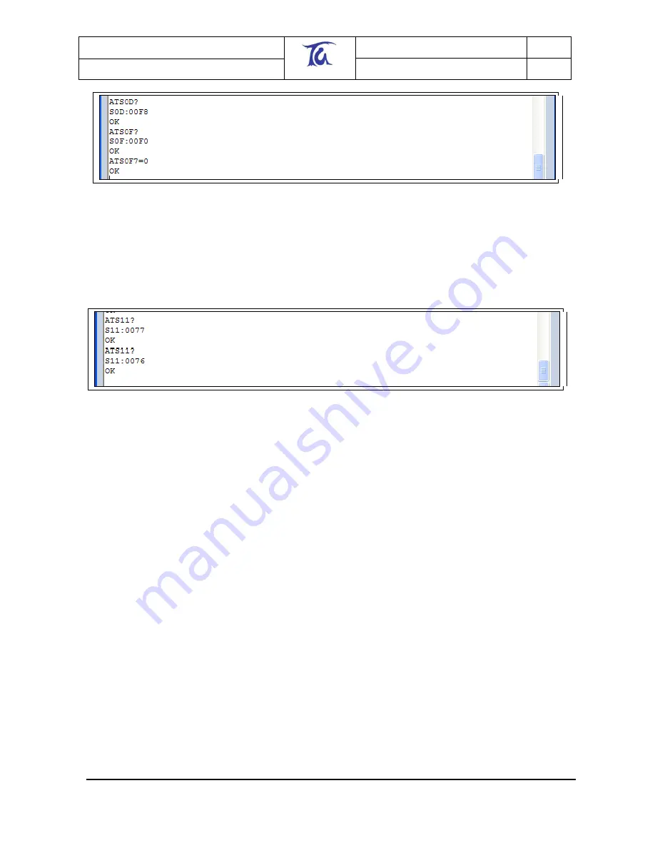
We can now check the status of the I/O by reading S11. Try to read S11 on the local node and
then read it again while pressing button 4 on the devkit. The results should appear as below:
Figure 14. Change in input values
It can be seen that bit 7 of register S11 is still set to 0 since we had switched on LED1,which is
connected to I/O7 previously (if you simply need to read the status of this bit you could also use
ATS117?). You can see when pressing button 4, bit 0 of S11 changes to zero as pressing a button
on the devboard forces the respective I/O to ground.
[Note: the commands “AT+ADLOC” and “AT+ADREM” of the R1xx firmware have been removed.
(Simply read registers S12 & S13.)]
5.5 Event Management (S15-S28)
Registers in this block trigger define the actions for ten events, based on interrupts or timers. Most
of the timer-related registers are used in pairs: One sets a timer threshold, the other defines an
action that is triggered after the timer expires. The counter threshold is set in quarter-second ticks,
e.g. 00F0 = 15x16 ticks = 60 seconds. The number in the action register corresponds to an entry
in the Built-in Functionality table described in section 11.
5.5.1 Interrupts
S15 defines the action taken on IRQ0 and S16, the action on IRQ1. S2E determines what causes
IRQ0 and IRQ1: Set bit 0(1) to trigger IRQ0 on a rising(falling) edge of I/O pin 0, set bit 2(3) to
send IRQ1 on a rising(falling) edge of I/O pin 1. The default actions defined in S15 and S16 is to
wake the module up to power mode 0 on either interrupt.


