Operating Information
2- 4
TLA721 Benchtop & TLA7XM Expansion Mainframe Service Manual
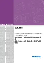
Figure 2--3 shows the rear view of the mainframe along with some of the key
connectors.
Fuse
AC Power
25-Pin PASSIVE
MONITOR connector
Fan speed switch
Figure 2- 3: Rear view of the benchtop chassis
The AC power connector is located on the rear bottom left side of the instru-
ment. The AC fuse holder is located just above the power connector.
The chassis ground screw can be used to connect more than one instrument to a
common ground point.
The fan speed switch controls the speed of the fan (blower). When the switch is
set to the VAR (variable) position, the mainframe automatically controls the
speed of the blower depending on the air temperature and amount of cooling
required by the modules. When the switch is in the FULL position, the blower
operates at full speed.
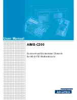
The 25-pin Sub-D connector lets you monitor the power supply voltages, fan
speed, and the maximum slot temperature rise within the mainframe.
The connector also provides remote on and off capability and access to the SYS-
RESET* and ACFAIL* signals.
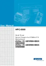
Figure 2--4 shows the location of the Passive Monitor Connector. Table 2--1 lists
the pin out of the Passive Monitor Connector and its function.
AC Power Connector
Chassis Ground Screw
Fan Speed Switch
Passive Monitor
Connector
Summary of Contents for TLA7XM
Page 5: ......
Page 13: ...Table of Contents viii TLA721 Benchtop TLA7XM Expansion Mainframe Service Manual ...
Page 17: ...Service Safety Summary xii TLA721 Benchtop TLA7XM Expansion Mainframe Service Manual ...
Page 21: ...Preface xvi TLA721 Benchtop TLA7XM Expansion Mainframe Service Manual ...
Page 25: ...Introduction xx TLA721 Benchtop TLA7XM Expansion Mainframe Service Manual ...
Page 43: ...Specifications 1 18 TLA721 Benchtop TLA7XM Expansion Mainframe Service Manual ...
Page 85: ......
Page 87: ...Adjustment Procedures 5 2 TLA721 Benchtop TLA7XM Expansion Mainframe Service Manual ...
Page 161: ...Repackaging Instructions 6 74 TLA721 Benchtop TLA7XM Expansion Mainframe Service Manual ...
Page 165: ...Electrical Parts List 8 2 TLA721 Benchtop TLA7XM Expansion Mainframe Service Manual ...
Page 169: ...Diagrams 9 4 TLA721 Benchtop TLA7XM Expansion Mainframe Service Manual ...
Page 189: ...Mechanical Parts List 10 20 TLA721 Benchtop TLA7XM Expansion Mainframe Service Manual ...