


Pulse Pro
fi
ling Application
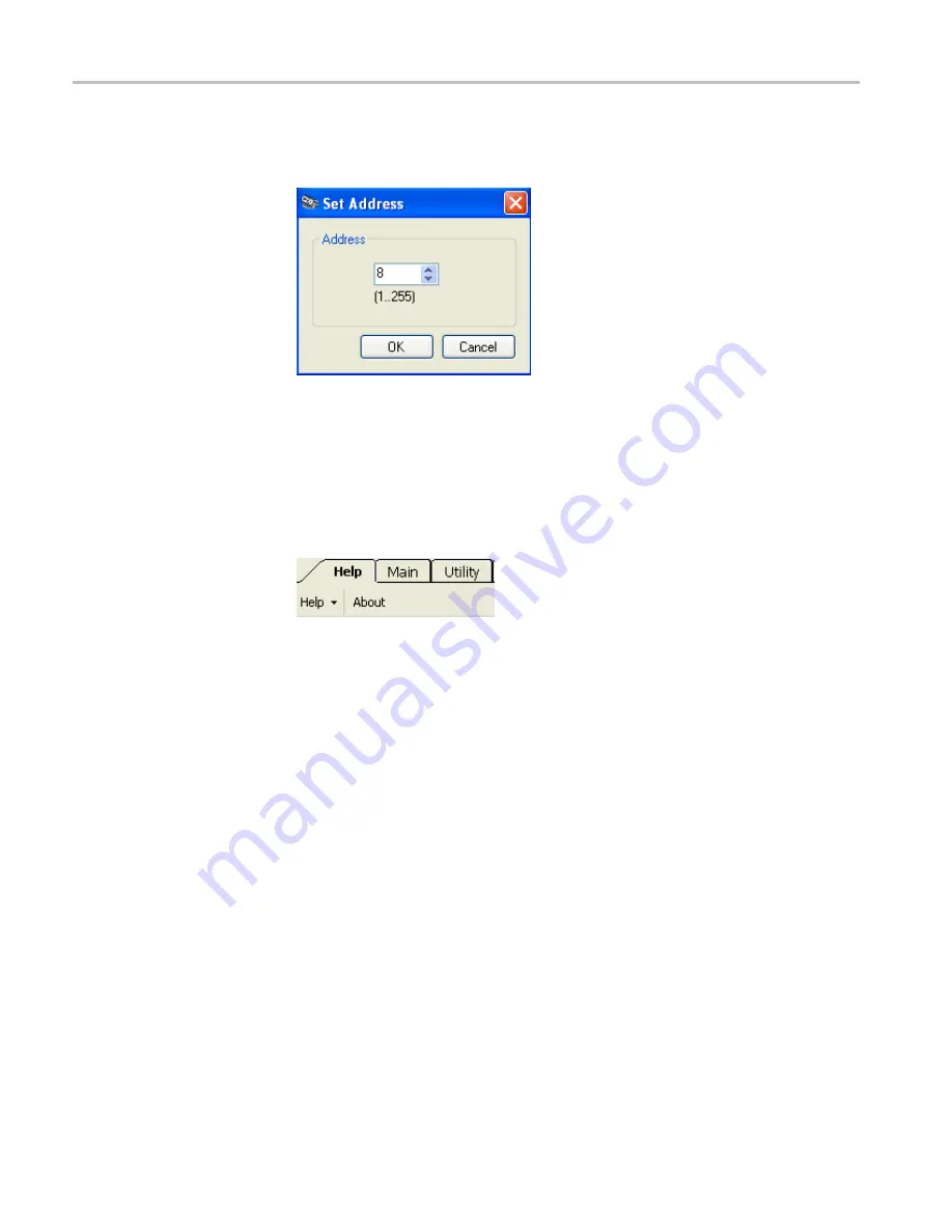
Set Address.
Click this button to set the instrument address. This is particularly
useful when multiple instruments are connected to a computer.
Recall Factory Setup.
Click this button to reset all measurement parameters and
user preferences, such as display colors and fonts, to default settings.
Help
The
Help
drop down menu provides access to a help document for this application
and a link to the Tektronix Web site to download user manuals. Click
About
to
view software,
fi
rmware, and driver version information.
Make a Marker Measurement
Pulse width measurements are normally de
fi
ned as the time between the 3 dB
points on the rising and falling edges of a pulse. When using markers for a
measurement like this, the results are highly dependent on the placement of the
markers. Placing markers at the precise 3 dB down points can be problematic for
pulses with very fast rise and fall times.
Follow this procedure to make a marker measurement of a pulse width:
1.
Highlight a single pulse in the Measurement Trace window. (See page 32,
2.
Zoom in on the pulse to position the marker for a Pulse Width measurement.
3.
Select
Markers
from the toolbar.
4.
Click on the
Marker 1
down arrow and select the
Normal
marker type.
Notice that Marker
1
appears in the Measurement window at center graticule.
48
RF and Microwave Power Sensors/Meters
Summary of Contents for PSM3000 Series
Page 2: ......
Page 6: ......
Page 10: ...Table of Contents iv RF and Microwave Power Sensors Meters...
Page 14: ...Preface viii RF and Microwave Power Sensors Meters...
Page 26: ...Getting Started 12 RF and Microwave Power Sensors Meters...
Page 32: ...Operating Basics 18 RF and Microwave Power Sensors Meters...
Page 74: ...High Speed Logger Application 60 RF and Microwave Power Sensors Meters...


