Performance Verification
54
OI1125 E/O Transmitter Instruction Manual
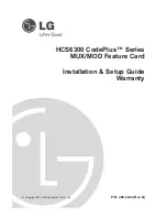
After you rename Meas 1 to Meas 4, when you take measurements, the data
displays on the right side of the oscilloscope screen, from Extinction Ratio (dB)
down to Average Optical Power (dBm). (See Figure 19). This measurement
order is repeated left to right in the rows in Tables 19 through 21 in the Test
Record.
4. Select the Acq tab to set the acquisition parameters.
a. In the Stop After box, select Condition.
b. In the Condition field, select Number of Acquisitions from the drop-
down menu.
c.
Enter 300 (# of acquisitions) in the field below the Condition field.
d. In the Stop Action box, select None.
5. Close the Setup window.
6. Press the Run/Stop button on the oscilloscope to begin a measurement.
The oscilloscope displays an eye pattern as shown in Figure 19.
Measurement data
Mask hits
Figure 19: Measurements taken from the eye pattern
Summary of Contents for OI1125
Page 4: ......
Page 8: ...Table of Contents iv OI1125 E O Transmitter Instruction Manual...
Page 20: ...Getting Started 8 OI1125 E O Transmitter Instruction Manual...
Page 30: ...Operating Basics 18 OI1125 E O Transmitter Instruction Manual...
Page 36: ...Specifications 24 OI1125 E O Transmitter Instruction Manual...
Page 38: ......
Page 42: ...Theory of Operation 30 OI1125 E O Transmitter Instruction Manual...
Page 72: ...Performance Verification 60 OI1125 E O Transmitter Instruction Manual...