9
I n s t r u c t i o n m a n u a l
6
ENG
FIRST PART
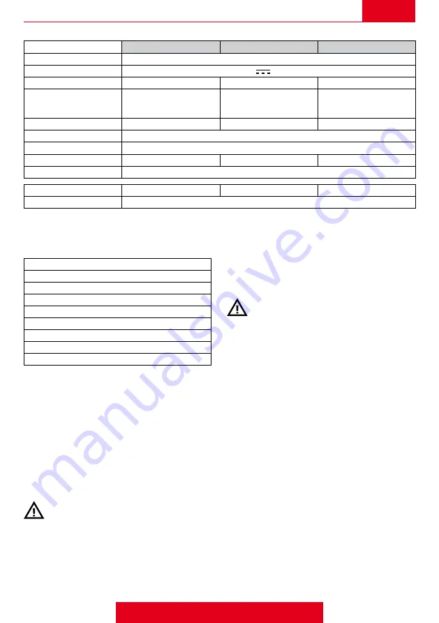
TECHNICAL DATA AND DIMENSIONS
Model
VGME1
VGME4
VGME5
Type
3-way distributor
Voltage
12V
(±10%)
Current
5.0 A
1.2 A
1.2 A
Max operating pressure
P/N 8370010 20 bar (290 psi)
P/N 8370014 10 bar (145 psi)
P/N 8370015 20 bar (290 psi)
P/N 8370016 30 bar (435 psi)
P/N 8370021 10 bar (145 psi)
P/N 8370022 20 bar (290 psi)
Maximum flow-rate
210 l/min (55.5 US gpm)
180 l/min (47.5 US gpm)
300 l/min (79 US gpm)
Max operating temperature
+5°C ÷ +60°C
Type of electrical connector
DIN 43650 A
Weight
2.6 kg
1.8 kg
2.5 kg
Dimensions
See Fig.1
Liquid inlet connector
Ø 19/25/35 mm
G3/4 M - Ø25 mm - G1 M
Ø 19/25/35 mm
Liquid outlet connector
G1 M - Ø 35/40 mm
The characteristics and technical data are merely indicative. The manufacturer reserves the right to add any modifica
-
tions considered necessary to the valve at any time.
IDENTIFICATION OF COMPONENTS (FIG. 2-3-4)
1
Pressure adjustment knobe
2
Valve drive motor
3
Pins for electrical connection
4
liquid inlet
5
liquid outlet
6
Liquid discharge (by-pass)
7
Connection pin protector cap
8
Fitting blocking fork
9
Technical data plate
OPERATION (FIG. 2-3-4)
The general valves of the VGME1 - VGME4 - VGME5
series are used to control the flow of liquid and to discharge
any in excess.
To control the valve opening and closing, use the dedicated
switch on the electrical control panel. To establish at which
pressure the excess liquid is to be discharged (maximum
pressure), adjust the valve by turning the knob 1: turn
clockwise to increase the pressure and turn counter-
clockwise to reduce it. The maximum pressure must be
adjusted while the valve is working (delivery open - control
switch turned ON).
The adjusted pressure must never exceed the
rated pressure of the system.
STARTING, STOPPING AND LAYING UP
Please refer to the instructions of the equipment on which
the valve is installed.
ROUTINE MAINTENANCE
- Periodically make sure the valve’s inlet filter is clean (if
fitted on the equipment).
- After each treatment, rinse the equipment thoroughly
with clean water. Do not use solvents or similar products.
Periodically make sure the blocking fork is inserted properly.
- Periodically check the condition of the piping and that it
is connected properly.
- Do not leave the valve idle with liquid inside it. Internal
parts will deteriorate quicker if the equipment remains idle
for more than a few days.
- If, during the winter break, the equipment is exposed to
temperatures below 4°C, pour anti-freeze liquid (as used
in cars) into the liquid circuit.
- When work is regained, drain the anti-freeze and carefully
wash out the equipment with clean water. Also ensure the
valve is working properly.
DISMANTLING AND DISPOSAL
The valve is to be demolished exclusively by qualified
personnel and in compliance with laws in force in the
country in which it is installed.
Summary of Contents for 8370014
Page 3: ...Fig 9 Fig 6 Fig 10 Fig 12 Fig 8 kit 6 Fig 7 kit 6 kit 6 Fig 11 ...
Page 25: ...Note ...
Page 26: ...Note ...
Page 27: ......


