background image

ITALIANO 

UPS EVO DSP MM RM 

41


Manuale utente 


5.2.1


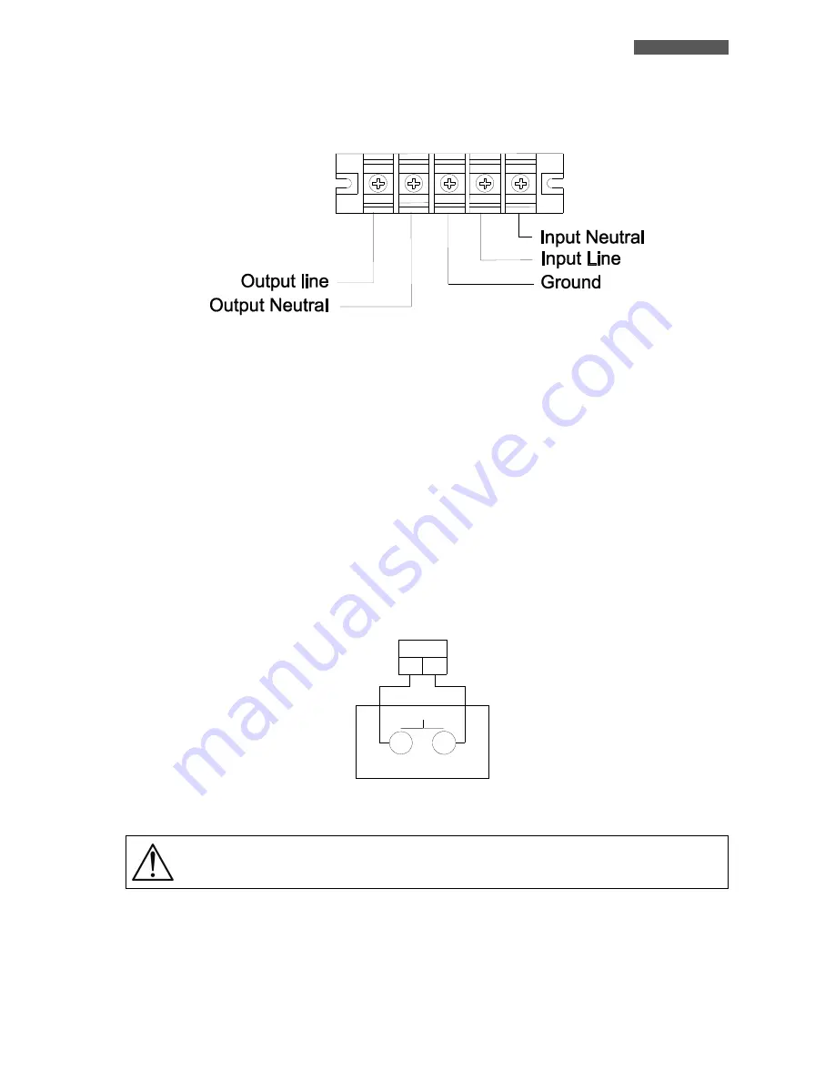
Morsettiera d’Ingresso/Uscita 


Figura 5 – Morsettiera d’Ingresso/Uscita 


Terminali INPUT

: per collegare la Rete Elettrica d’Ingresso. 


Terminali OUTPUT

: per collegare la linea d’Uscita OUTPUT. 


Terminale GROUND

: per collegare i cavi GROUND della Rete Elettrica d’Ingresso e della linea d’Uscita. 


5.2.2   EPO (Emergency Power OFF) 

I  prodotti  EVO  DSP  MM  RM  hanno  sul  retro  il  connettore  per  EPO  (Emergency  Power  OFF)  (vedi  figura  6), 

che 

permette di disattivare immediatamente l’Uscita dell’UPS a distanza in caso di emergenza.  

Il  prodotto  viene  fornito  con  i  terminali  dell’EPO  cortocircuitati  e  in  questo  caso  il  prodotto  funziona 
normalmente. 

Se si vuole utilizzare un interruttore esterno per attivare lo spegnimento EPO, allora rimuovere il cortocircuito dai 
terminali e collegare l’interruttore ai terminali, come descritto nella figura 6.  


EPO

1

2

Interruttore remoto

           EPO


Figura 6 – EPO (Emergency Power OFF) 


Se  l’interruttore  è  CHIUSO  il  prodotto  funziona  regolarmente,  se  l’interruttore  viene 
APERTO allora l’Uscita dell’UPS si disattiva immediatamente. 


Per riattivare l’Uscita UPS l’UPS dopo uno spegnimento EPO, occorre richiudere l’interruttore di EPO. 

I  terminali  di  EPO  non  richiedono  una  Tensione  esterna  di  alimentazione  e  sono  isolati  dalle  tensioni 
pericolose presenti all’interno dell’UPS. 

Summary of Contents for EVO DSP MM 10.0

Page 1: ...Uninterruptible Power Supply EVO DSP MM 6 0 Rack Mount EVO DSP MM 10 0 Rack Mount User s manual Manuale utente...

Page 2: ......

Page 3: ...5 2 1 Input Output Terminals 13 5 2 2 EPO Emergency Power Off 13 6 Electrical Installation 14 6 1 Installation 15 7 First Start Up 16 8 Functioning 17 8 1 Turning ON and OFF 17 8 2 Low Battery and Aut...

Page 4: ...5 2 1 Morsettiera d Ingresso Uscita 41 5 2 2 EPO Emergency Power OFF 41 6 Installazione Elettrica 42 6 1 Installazione 43 7 Prima Accensione 44 8 Funzionamento 45 8 1 Accensione e Spegnimento 45 8 2 F...

Page 5: ...clusively by qualified technical personnel authorized by TECNOWARE TECNOWARE declines any responsibility if this warning is disregarded Warning to the technical personnel authorized for Service since...

Page 6: ...power failure or a Low Battery condition this allows automatic data backup during an extended blackout with the most common operating systems Windows Linux Unix etc Thanks to Interfaces UPS DSP MM RM...

Page 7: ...tional EPO Emergency Power OFF Communication with the computer through RS 232 and USB interfaces Available extended autonomy by adding external Battery Boxes ECO functioning mode selectable Frequency...

Page 8: ...at least 10 cm of unobstructed space all around the UPS in order to keep it properly ventilated Do not obstruct ventilation holes Do not insert objects or pour liquids in the ventilation holes Do not...

Page 9: ...batteries supply the required Output power thanks to the DC AC conversion carried out by the Inverter The UPS switches back to Normal mode a few seconds after AC Input power is restored or Voltage co...

Page 10: ...mode does not provide perfect stability in Frequency waveform RMS value of the Output Voltage like in Normal mode Thus the use of this mode should be carefully executed according to the level of prot...

Page 11: ...meters Front panel shown below consists of three parts 1 Graphic LCD panel provides complete information about the energy flow path and existing alarms Load and Battery level Input Output and Battery...

Page 12: ...tion Indicates the warning that a fault has occurred Indicates the Fault codes and the codes are listed in the Fault Table of chapter 8 Mute operation Indicates that the UPS alarm is disabled muted Ou...

Page 13: ...ates the UPS connects to the mains Indicates the Battery is working Indicates the Bypass circuit is working Indicates the ECO mode is enabled Indicates the Inverter circuit is working Indicates the Ou...

Page 14: ...n more than 0 5 sec to test the Battery while in Normal mode MUTE Mute the alarm press and hold the button more than 0 5 sec to mute the buzzer If you press it again after the buzzer is muted the buzz...

Page 15: ...arger failure Input Circuit failure Overload 3 times in 30 min Fault Vdc Bus Start failure Beeping continuously YES Vdc Bus Over Vdc Bus under Vdc Bus Unbalance Vdc Bus short circuit Inverter Soft Sta...

Page 16: ...ic cover of Battery connector UPS unit remove the metal cover to access to the Battery connector and to connect the UPS unit to the Battery Box unit by the included Battery cable 10 Charger and Power...

Page 17: ...EPO short circuited terminals and in this case the product works normally If you want to use an external switch to turn OFF the UPS by EPO then remove the short circuit from the EPO terminals and conn...

Page 18: ...tion procedure be sure that 1 The Input circuit breaker of UPS unit is OFF see figure 4 2 The Battery circuit breaker of Battery Box unit is OFF see figure 4 3 The AC Input Voltage for the UPS has bee...

Page 19: ...es access to the UPS terminals The instructions below describe the operations to correctly connect the UPS unit to the Battery Box unit ATTENTION the UPS unit doesn t work without Battery Box unit bec...

Page 20: ...Up the following procedure is observed for greater safety 1 Turn ON the Battery circuit breaker of the Battery Box unit see figure 4 2 Check if the Input circuit breaker the rear side of UPS unit is i...

Page 21: ...ery Box unit in OFF position Place the Input circuit breaker in OFF position The graphic LCD panel and the leds on the front panel are OFF only when the UPS is completely OFF If UPS is used daily it i...

Page 22: ...The UPS recharges batteries automatically if it works in Normal mode or in Bypass mode 8 3 Load Testing The UPS indicates the Output Load level by graphic LCD on the right side as described in the cha...

Page 23: ...ery Status when the UPS is running in Normal mode Converter Frequency mode ECO mode you could press the TEST button to let the UPS do the Battery Test The Battery Test starts immediately and it finish...

Page 24: ...Fan failure Over temperature Beeping every second Battery Charger failure Beeping every second Input Circuit failure Beeping every second Overload 3 times in 30 min Beeping every second Warning Table...

Page 25: ...s On the UPS rear side there are the connections of the Interfaces Only one of the RS232 USB communications can be activated at one time To activate RS232 communication it is sufficient to connect the...

Page 26: ...Normal mode 7 Input Power Factor 0 99 at 100 Load OUTPUT Nominal Voltage Single Phase 208 220 230 240 Vac selectable Voltage Regulation 1 Inverter Waveform True Sinewave Nominal Frequency 50 60 Hz sel...

Page 27: ...indows Linux Novell SNMP Interface Optional OTHERS EPO Emergency Power OFF Included External Bypass Contact Included ECO Mode Selectable Frequency Converter Mode Selectable Technical data may change w...

Page 28: ...nput Line then turn off the Battery circuit breaker of the Battery Box unit disconnect the Battery cable and disconnect the Input cable for recharging batteries Then remove the front panel of the Batt...

Page 29: ...nel authorized by TECNOWARE TECNOWARE declines any responsibility if this warning is disregarded Warning to the technical personnel authorized for service since internal components are connected to th...

Page 30: ...automatically because short circuit occurs on the UPS Output Check Output wiring or if connected devices are in short circuit status Fault code is shown as 1 2 3 4 5 11 12 13 1A 21 24 35 36 41 or 42 o...

Page 31: ...s may be needed to prevent disturbances Product Disposal UPS EVO DSP MM RM cannot be disposed as an urban waste but must be treated as a separate waste Any violation is indictable with financial sanct...

Page 32: ...ENGLISH User s manual 28 UPS EVO DSP MM RM...

Page 33: ...a manutenzione da parte dell utente Interventi tecnici di qualsiasi tipo devono essere compiuti solo da personale tecnico specializzato ed autorizzato da TECNOWARE In caso contrario TECNOWARE declina...

Page 34: ...mputer le condizioni di assenza Rete e di fine autonomia ci rende possibile lo svolgimento delle funzioni di salvataggio automatico dei dati durante un black out prolungato con i pi diffusi sistemi op...

Page 35: ...P opzionale EPO Emergency power OFF Comunicazione con il computer tramite interfacce RS 232 e USB Autonomia batterie espandibile tramite ulteriori unit Box Batterie Modo di funzionamento ECO seleziona...

Page 36: ...asciare uno spazio libero di almeno 10 cm sia lateralmente che sul retro dell UPS per permetterne una sufficiente areazione Non ostruire le fessure o i fori di ventilazione Non inserire oggetti o vers...

Page 37: ...potenza necessaria in Uscita grazie sempre alla conversione CC CA svolta dall Inverter Quando la Tensione di Rete viene ripristinata oppure l ampiezza della Tensione rientra all interno delle specifi...

Page 38: ...O non garantisce perfetta stabilit in frequenza forma d onda valore RMS della Tensione d Uscita come il modo Normale di funzionamento Quindi l uso del modo ECO deve essere utilizzato solo in accordo c...

Page 39: ...LCD grafico che fornisce le informazioni complete sul percorso del flusso energia per i vari modi di funzionamento sugli allarmi esistenti sul carico in Uscita sulle batterie e sulle misure delle gra...

Page 40: ...i Guasto Fault Indica il codice di Fault la lista dei codici riportata nella tabella Tabella Fault nel capitolo 8 Informazioni Allarme Acustico Indica che l allarme acustico disabilitato Informazioni...

Page 41: ...linea elettrica d Ingresso Indica che la Batteria attiva Indica che il blocco Bypass attivo Indica che stato attivato il modo ECO Indica che il blocco Inverter attivo Indica che l Uscita UPS attiva In...

Page 42: ...pi di 0 5 secondi durante il funzionamento in modo Normale MUTE Disattiva attiva l allarme acustico per disattivare l allarme acustico premere e mantenere premuto il pulsante per pi di 0 5 secondi Se...

Page 43: ...uasto Carica Batteria Guasto Circuito Ingresso Rete Overload 3 volte in 30 minuti Guasto Fault Guasto Start Vdc Bus Allarme acustico continuo SI Vdc Bus Alta Vdc Bus Bassa Vdc Bus Non Bilanciata Corto...

Page 44: ...gresso Uscita rimuovendolo si accede alla morsettiera per i collegamenti di potenza vedi figura 5 9 Coperchio metallico di protezione del connettore batterie 10 Ventole di raffreddamento dei circuiti...

Page 45: ...odotto viene fornito con i terminali dell EPO cortocircuitati e in questo caso il prodotto funziona normalmente Se si vuole utilizzare un interruttore esterno per attivare lo spegnimento EPO allora ri...

Page 46: ...ura d installazione accertarsi che 1 L interruttore Ingresso Rete dell unit UPS sia OFF vedi figura 4 2 L interruttore Batterie dell unit Box Batterie sul retro sia OFF vedi figura 4 3 La linea elettr...

Page 47: ...descritte sotto descrivono le operazioni da svolgere per collegare correttamente l unit UPS all unit Box Batterie ATTENZIONE l unit UPS non contiene batterie Per fare funzionare l unit UPS necessario...

Page 48: ...ntrollare che l interruttore Ingresso Rete dell unit UPS sia in posizione OFF vedere figura 4 3 Controllare che nessun carico sia collegato alle Uscite dell UPS 4 Controllare che l ampiezza della Tens...

Page 49: ...rontale sono spenti solo quando l UPS completamente spento Se si utilizza quotidianamente l UPS si consiglia di lasciare sempre l interruttore Ingresso Rete in posizione ON e utilizzare i pulsanti ON...

Page 50: ...o e funzionante in modo Normale o in modo Bypass 8 3 Controllo del Carico L UPS indica il livello del carico in Uscita per mezzo del display grafico visualizzandolo a destra come descritto nel capitol...

Page 51: ...amento in modo Normale in modo ECO e in modo Convertitore di Frequenza Per svolgere il Test Batteria sufficiente premere il pulsante TEST del pannello frontale il test si avvia immediatamente e si con...

Page 52: ...o Carica Batteria Allarme acustico ogni secondo Guasto Circuito Ingresso Rete Allarme acustico ogni secondo Overload 3 volte in 30 minuti Allarme acustico ogni secondo Tabella Allarmi 8 7 Segnalazioni...

Page 53: ...ne con un Personal Computer Infatti sul retro sono presenti i connettori delle Interfacce Le Interfacce di Comunicazione RS232 e USB non possono essere attive contemporaneamente Per attivare la comuni...

Page 54: ...di Potenza d Ingresso 0 99 con carico al 100 USCITA Tensione Nominale Monofase 208 220 230 240 Vac selezionabile Regolazione Tensione 1 Forma d Onda Inverter Sinusoidale Frequenza Nominale 50 60 Hz s...

Page 55: ...nux Novell Interfaccia SNMP Opzionale ALTRE SPECIFICHE EPO Emergency Power OFF Incluso Contatto per Bypass esterno Incluso Modo ECO Selezionabile Modo Convertitore di Frequenza Selezionabile I dati te...

Page 56: ...are su OFF l interruttore Batterie dell unit Box Batterie scollegare il cavo Batterie e scollegare il cavo d ingresso per la ricarica delle batterie Quindi togliere il pannello frontale dell unit Box...

Page 57: ...evono essere compiuti solo da personale tecnico specializzato ed autorizzato da TECNOWARE In caso contrario TECNOWARE declina ogni sua responsabilit Avviso per il personale tecnico autorizzato alla ma...

Page 58: ...acustico suona continuamente L UPS si disattivato automaticamente perch si verificato un cortocircuito in Uscita dell UPS Controllare i collegamenti d Uscita e se uno dei dispositivi collegati in Usci...

Page 59: ...untive per prevenire disturbi Smaltimento del Prodotto Il prodotto EVO DSP MM RM non pu essere smaltito come rifiuto urbano ma deve esserlo tramite raccolta separata qualsiasi violazione punita con sa...

Page 60: ...ITALIANO Manuale utente 56 UPS EVO DSP MM RM...

Page 61: ......

Page 62: ......

Page 63: ...hts reserved All trademarks are property of their respective owners TECNOWARE s r l Via Montetrini 2E Molino del Piano Florence Italy www tecnoware com This manual has been printed and edited by TECNO...

Page 64: ...TECNOWARE s r l www tecnoware com...

Reviews: