ENGLISH
User’s manual
12
UPS EVO DSP MM RM
5.2
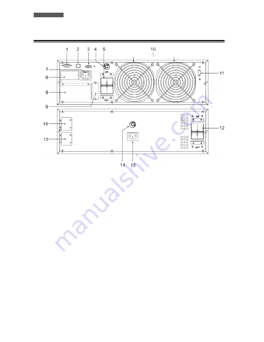
Rear Side
Figure 4 – above: UPS unit; below: BATTERY BOX unit
1.
Computer Interface (DB9 female connector
): it is the communication RS-232 port.
2.
Computer Interface (USB connector):
it is the communication USB port.
3.
EPO (Emergency Power OFF) connector
4.
Output fuse breaker
: for Output receptacle IEC type (#7); 10A max current.
5.
Input circuit breaker
6.
Slot for SNMP Interface (optional)
7.
Output receptacle (IEC C13 type):
to supply small critical loads.
8.
Metallic panel for access to the Input/Output terminals:
upon removal, it is possible to access the
Input/Output terminals (see figure 5).
9.
Metallic cover of Battery connector (UPS unit):
remove the metal cover to access to the Battery connector
and to connect the UPS unit to the Battery Box unit by the included Battery cable.
10.
Charger and Power stage fans
11.
External Manual Bypass terminals (EMBS)
12.
Battery circuit breaker:
to cut Battery voltage from UPS unit
.
13.
Grounded AC Input power socket, for recharging batteries:
(IEC C14 type); only connecting this socket to
an AC Input line by the included power cable, it is possible to recharge the batteries inside the box.
14.
Input fuse breaker
: for Input socket (#14); 10A max current.
15.
Metallic cover of Battery connector (Battery Box unit):
remove the metal cover to access to the Battery
Connector and to connect the Battery Box unit to the UPS unit, or to connect the Battery Box unit to a
further Battery Box unit.
16.
As point 15.
Summary of Contents for EVO DSP MM 10.0
Page 2: ......
Page 32: ...ENGLISH User s manual 28 UPS EVO DSP MM RM...
Page 60: ...ITALIANO Manuale utente 56 UPS EVO DSP MM RM...
Page 61: ......
Page 62: ......


