


The motor should be connected to
using shielded 2-wire cable. Make sure that
shield is connected properly to GND at one end only. Leaving shield disconnected may cause
excessive EMC noise. See chapter
on page 29 to check the order of wire
connections.
3.5.
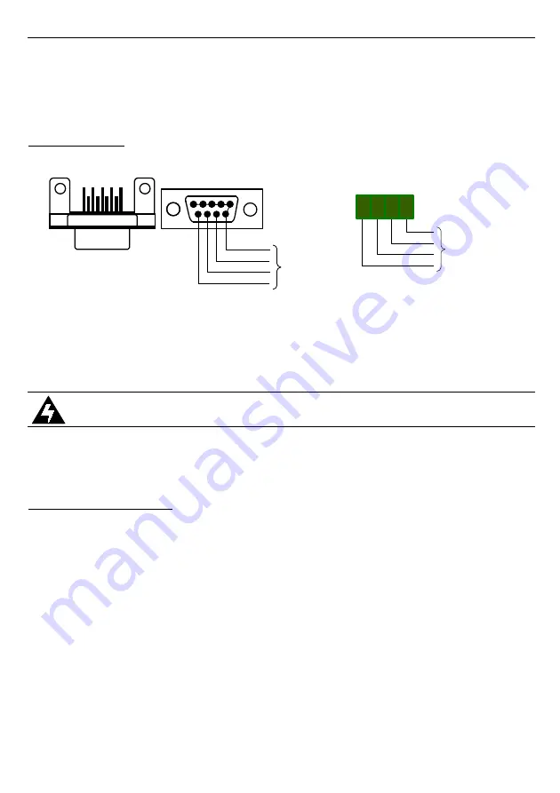
ENCODER
A)
B)
Fig. 3.4. Encoder connection of
controller
The controller is designed to work with motors equipped with 5V quadrature encoders,
generating from 150 to 999 pulses per centimetre of door's linear movement. Typically
encoder cables are terminated with a Canon DB-9 connector. The
has a DB-9 socket
on board in order to facilitate fast and convenient installation. (Figure 3.4 A).
CAUTION!
Make sure that encoder signal pins match
connector to avoid damage to the controller.
If the encoder cable is not terminated with Canon DB-9 connector, the encoder can be
board's screw terminals as shown in figure 3.4B.
3.6.
CONTROL INPUTS
controller is equipped with two control inputs provided for compatibility with
different types of elevator controllers. Both inputs or either of them individually can be
activated from the menu of the controller. Connection alternatives are shown below.
Figures 3.5 A and B shows how to connect open/close control signals to
{CLOSE INP.}
and
{OPEN INP.}
. The control signals are generated by the main
controller of the elevator. If the elevator control system uses normally-open potential-free
contacts (e.g. relay) to control the doors they can be connected to
3.5A utilising the on-board voltage source of the controller. If the elevator control system uses
voltage outputs to control doors, they can be connected to
as shown in fig. 3.5B.
Make sure that both inputs are activated in the controller's menu.
9
J5
1 2 3 4
TO
ENCODER
+5V
SIGNAL A
SIGNAL B
0V
1
6
9
5
TO
ENCODER
0V
SIGNAL B
SIGNAL A
+5V
J4
J4


