BIKE XT: Service & Maintenance manual - rev. 2.0
Page 6.3
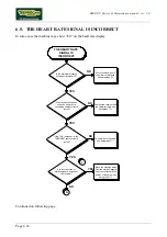
NO
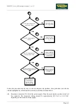
Do all DC voltages reach the
display?
Do all DC voltages reach the
alternator interface board
Are all DC voltages present on the
output of the alternator interface
board?
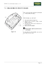
Replace the CPU
board: see paragraph
7.3.
Replace cable BK-6
connecting the power
supply to the alternator
interface board
Replace the alternator
interface board: see
paragraph 7.8.
Replace cable BX-1
connecting the
alternator interface
board to the display
YES
NO
NO
YES
NO
YES
4
5
6
Are DC output voltages of the
power supply correct?
3
Replace the power
supply: see paragraph
7.8.
YES
A
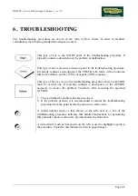
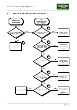
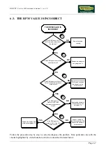
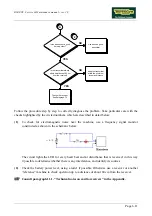
Follow the procedure step by step to correctly diagnose the problem. Take particular care with the
checks highlighted by circled numbers, which are described in detail below:
(1)
Disconnect connector CN1 from the power supply. Place the tester probes on pins 4 and 6 of
the connector. The measured voltage should be approximately 220 VAC or 110 VAC
depending on the mains electricity supply.
Summary of Contents for BIKE XT
Page 1: ...SERVICE MAINTENANCE MANUAL REV 2 0...
Page 2: ......
Page 4: ......
Page 16: ...BIKE XT Service Maintenance manual rev 2 0 Page 4 2 Page intentionally left blank...
Page 30: ...BIKE XT Service Maintenance manual rev 2 0 Page 6 12 Page intentionally left blank...
Page 46: ...BIKE XT Service Maintenance manual rev 2 0 Page 7 16 Page intentionally left blank...
Page 54: ...BIKE XT Service Maintenance manual rev 2 0 Page 8 8 Page intentionally left blank...
Page 58: ...BIKE XT Service Maintenance manual rev 2 0 Page 9 4 Page intentionally left blank...
Page 66: ...BIKE XT Service Maintenance manual rev 2 0 Page 11 6 Page intentionally left blank...
Page 67: ......


