background image

User manual 57

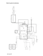
Electric system circuits draw

Summary of Contents for Plasma CUT 105

Page 1: ...h 8m Plasma CUT 85 Item number 294 005010 00000 CUT 85 with torch length 8m Plasma CUT 105 Item number 294 005020 00000 CUT 105 with torch length 8m Plasma CUT 125 Item number 294 005030 00000 CUT 125...

Page 2: ...10 Duty Cycle 11 Dimensions and weight of the power source 11 Specifications torches AP 65 125 12 Torches dimensions Hand torch dimensions 13 Mechanized torch dimensions with or without rail 13 SYMBO...

Page 3: ...sumables for 45 Amps 45 Mechanized unshielded consumables for 65 Amps 46 Mechanized unshielded consumables for 85 Amps 47 Mechanized unshielded consumables for 105 Amps 48 Mechanized unshielded consum...

Page 4: ...our customer service department on 49 2623 9276400 A list of authorised sales partners can be found at www teamwelder com Liability relating to the operation of this equipment is restricted solely to...

Page 5: ...general warning symbol The hazard is also highlighted using a symbol in the page margin CAUTION Working or operating procedures which must be closely observed to pre vent possible minor personal injur...

Page 6: ...way from the work area Make sure the work area is a fire extinguisher and that it is in top condition for use Ventilate the work area before using the slicer when working in areas of potential fire ri...

Page 7: ...n others about the dangers of noise FLYING SPARKS CAN INJURE During the cutting process there can be landslides incandescent material Itching can cause flying metal Use face shield and safety glasses...

Page 8: ...nvisible rays that can burn eyes and skin Use protective clothing made from durable flame resistant material and foot protection Use face protection helmet or shield with filter lenses to protect your...

Page 9: ...kness FE SS AL 50 45 40 mm FE SS AL 40 35 30 mm FE SS AL 35 30 25 mm FE SS AL 25 20 15 mm Optimum Cutting Thickness FE SS AL 40 35 30 mm FE SS AL 35 30 25mm FE SS AL 30 25 20 mm FE SS AL 20 15 10 mm A...

Page 10: ...ithout oil Clean mois ture free without oil Clean mois ture free without oil Clean mois ture free without oil Gas inlet pressure and flow 6 1 bar 200 l mm 6 1 bar 200 l mm 6 1 bar 200 l mm 6 1 bar 200...

Page 11: ...g The following diagram represents a duty cycle of 80 Dimensions and weight of the power source 8 minutes cutting 2 minutes resting Weight power source without torch Model CUT 65 85 32 kg 36 kg Model...

Page 12: ...Gouging capability metal removal rate on Mild Steel 6 kg h 8 kg h 10 kg h 12 kg h Weight Hand Lead 5m 2 03 kg without consumables Lead 8m 2 85 kg without consumables Lead 15m 4 74kg without consumabl...

Page 13: ...User manual 13 Torches dimensions Hand torch dimensions Mechanized torch dimensions with or without rail...

Page 14: ...source and torch are suitable for use in environment with danger of electrocution The hand torches consumable parts must be protected to meet the mark S IEC symbols It is possible that the following s...

Page 15: ...transit you should complain to the carrier TEAMWELDER given a copy of the invoice packing upon request If you need additional assistance please call Customer Service at the phone number listed at the...

Page 16: ...User manual 16 f f f Lift with crane Use an approved harness Keep the power source as horizontal as possible Keep in place the cover...

Page 17: ...erator capable of cutting at 380 400 Vac three phase Use a line disconnect breaker for each power input so that the operator can turn off the power supply quickly in an emergency Place the back of the...

Page 18: ...ire cord with a protective grounding green or green yellow and must comply with national and local electrical requirements Connecting to autonomous generator When using a generator to power the CUT 65...

Page 19: ...9 Three phase power cable CE models CUT 65 105 come with power cord 4 mm2 4 wires 3 phases plus ground CE models CUT 125 come with power cord 6 mm2 4 wires 3 phases plus ground To operate the CUT 65 1...

Page 20: ...Black Installation the plug A licensed and qualified electrician should connect the power cord to the plug The mass grip area Important Place dough in an area where no or primer or paint You have to g...

Page 21: ...allation the torch 1 TURN OFF the power source OFF 0 Turn OFF ON I Turn ON 2 Unplug the socket from the power net 3 Torch connector Safety Pin for connection of plasma torches only in accordance with...

Page 22: ...User manual 22 4 Addressing the key torch with key and dock connector Torch key Female machine key 5 Once faced and well coupled to the connector screw torch...

Page 23: ...gas supply is not good the cutting speed decrease cut quality will deteriorate diminish the ability to cut the required thickness and the life of the consumables will be shorte ned WARNING Do not allo...

Page 24: ...e closed with a black plastic cover 2 Air hose Use an inert gas hose with a minimum internal diameter of 10 mm and one attach of G1 4 or a female quick connecti on located also in the back side of the...

Page 25: ...ug the remote TEAMWELDER see Parts List for part numbers into the connector on the back panel Connecting the machine interface CNC Are available through the machine interface see the figure above sign...

Page 26: ...ed 1 0 mm2 single pair 300V or higher The arc voltage signal is accessible in the interface card machine as follows 1 Turn off the power of the plasma generator 2 Remove the screws that joined the top...

Page 27: ...rminal ends of type faston 6 35mm to connect to positive and negative Signal Arc voltage to use in the torch height control Type Output Note Full arc voltage Without voltage divisor 300Vdc maximum Pos...

Page 28: ...User manual 28 1 Torch 2 Star CNC 3 Arc Trans 4 Solenoid CNC plasma cutting table is starting the movement of the exes X or Y...

Page 29: ...User manual 29 CNC Activating external DC coil with an external power supply...

Page 30: ...User manual 30 CNC Activating an external AC coil with an external power supply...

Page 31: ...User manual 31 CNC Activating an industrial isolated module with an external power supply...

Page 32: ...User manual 32 OPERATIONS Controls and indicators...

Page 33: ...User manual 33 Control panel...

Page 34: ...User manual 34 Torch consumables installation Torch consumables configuration...

Page 35: ...User manual 35 Torch parts...

Page 36: ...User manual 36 Torch consumables configuration continued...

Page 37: ...User manual 37 Torch parts...

Page 38: ...t the pilot arc It is used to remove welding or gouging Switch ON I as shown Note The cooling fan will only work when the plasma needed Check that the gas pressure is above 3 bar in cutting and grid m...

Page 39: ...User manual 39 Check and adjust the gas pressure and current power...

Page 40: ...User manual 40 Operating the manual torch Operating the safety torch trigger...

Page 41: ...ng area to reduce exposure to electromagnetic fields EMC Do not hold the piece of piece to be release Cutting start from the edge of the piece Keep the nozzle of the torch upright at the edge of the p...

Page 42: ...elded consumables Please don t tighten down the torch to the work piece while cutting Slide the torch carefully along the work piece to obtain a perfect cut Put the torch along the cut is easier to dr...

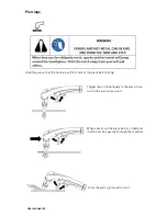
Page 43: ...nozzle is within 3 mm of the piece before firing Trigger the torch obliquely to the piece then turn to the vertical position When sparks out the piece below it indicates that the arc has passed throu...

Page 44: ...firing Hold the torch at an angle of 45 to the work piece Squeeze the trigger to get a pilot arc Transfer the plasma arc to the work piece Maintain an approximately 45 angle of the work piece Lean in...

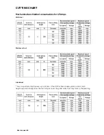
Page 45: ...es for 45 Amps Mild steel Stainless steel Aluminum You can perform thicknesses up to 32 mm If the CNC software and system control torch height up provisionally allow the torch to pass over the pond sc...

Page 46: ...User manual 46 Mechanized unshielded consumables for 65 Amps Mild steel Stainless steel Aluminum...

Page 47: ...User manual 47 Mechanized unshielded consumables for 85 Amps Mild steel Stainless steel Aluminum...

Page 48: ...User manual 48 Mechanized unshielded consumables for 105 Amps Mild steel Stainless steel Aluminum...

Page 49: ...User manual 49 Mechanized unshielded consumables for 125 Amps Mild steel Stainless steel Aluminum...

Page 50: ...not worn Each week Examine and check the safety switch for the cap note the red fault light and yellow light of the holding cap of the torch which illuminate when the cap is loose Every 3 months Repla...

Page 51: ...User manual 51 Consumables inspection...

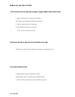
Page 52: ...n the filter bowl until it releases D Pull the filter bowl down to remove Note Do not discard the O ring Remove the filter element from the filter housing Note Do not allow the filter element turn whe...

Page 53: ...cators Lighting indicators Normal and bevel cutting Discontinuous material cutting grid Gouging or remove welding Security indicator cap holding the torch On indicator signal START Indicator transferr...

Page 54: ...The display leds are flashing 3 1 The voltage of one the phases is very low Check the installation by an electrician 4 On the display appears HOT message 4 1 One of the internal switches thermostat h...

Page 55: ...heck the consumables in this section The gas pressure is incorrect Adjust the gas pressure See Setting and check gas pressure section 4 Check that the gas pressure in the power supply is not less than...

Page 56: ...rn Turn the power OFF and check consumables assembly line Technical questions If you cannot solve a problem by following this basic troubleshooting guide or if you need further assistance 1 Call your...

Page 57: ...User manual 57 Electric system circuits draw...

Page 58: ...User manual 58 PARTS Configuration of the torch consumables...

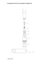
Page 59: ...User manual 59 Configuration of the torch consumables continuation...

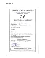
Page 60: ...User manual 60 DECLARATION OF CONFORMITY DOC TW CUT 65...

Page 61: ...User manual 61 DOC TW CUT 85...

Page 62: ...User manual 62 DOC TW CUT 105...

Page 63: ...User manual 63 DOC TW CUT 125...

Page 64: ...s Barcelona ESPA A Tel 937842918 Fax 937315226 http www tecnomec es tecnomec ballero com Technical data subject to change without notice No liability for printing errors Text and Illustrations are pro...

Reviews: