192
196
192
193
195
193
197
RADIO INSTALLATION
(Continued)
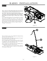
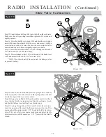
Figure 106
Figure 106
Figure 105
Figure 105
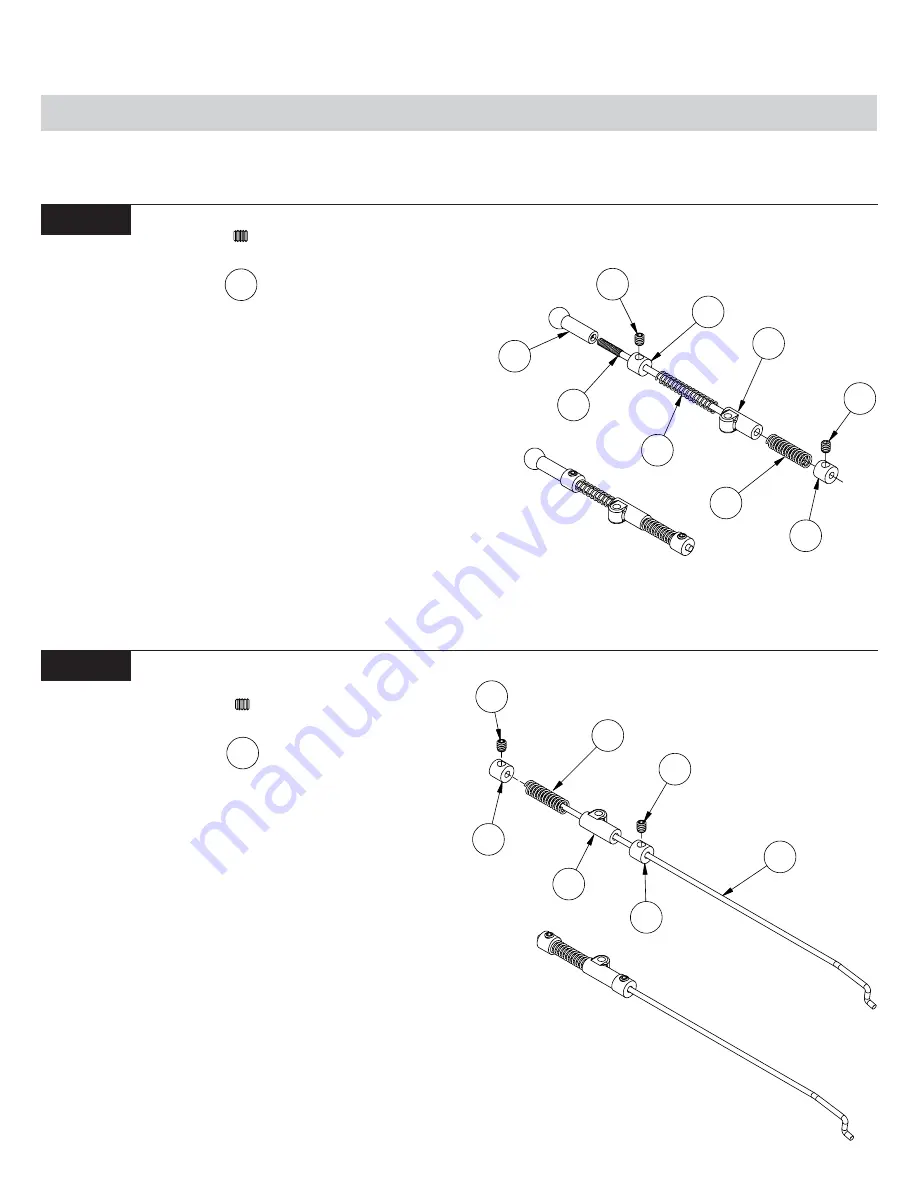
Slide Valve Carburetors
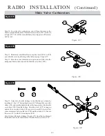
Step 24. Thread the 4mm ball cup (204) all the way onto the end of the
threaded throttle rod (203). Slide a linkage collar (192) over the other
end of the throttle rod (203), and up against the ball cup (204). Secure
the collar (192) with a 4-40 x 1/8" set screw (193).
Step 25. Place the throttle over-ride spring (194) (longer of the two
springs) over the rod (203) and against the collar (192). Slide a plastic
over-ride slider (195) onto the rod (203), so that the long end is away
from the ball cup (204).
Step 26. Place a brake over-ride spring (196) (black, shorter of the two
springs) over the rod (203) and against the over-ride slider (195).
Place a linkage collar (192) over the end of the rod (203), so the springs
are somewhat compressed, and secure it with a 4-40 x 1/8" setscrew
(193). The collar (192) should be positioned at the end of the rod
(203). Final adjustments will be made later.
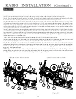
Step 27. Slide a linkage collar (192) over the end of the long, brake Z-
bend wire (197), and position it approximately 3" (75mm) from the Z-
bend. Secure the collar (192) in place with a 4-40 x 1/8" set screw
(193).
Step 28. Slide a plastic over-ride slider (195) onto the wire (197), so
that the long end is towards the Z-bend. Place a brake over-ride spring
(196) (black, shorter of the two springs) over the wire (197) and against
the slider (195).
Step 29. Slide a linkage collar (192) over the end of the wire (197) until
it just touches the spring (196). Secure it with a 4-40 x 1/8" setscrew
(193). Once again, final adjustments will be made later.
193
193
4 7
If your engine comes equipped with a slide valve carburetor, complete the steps in
Figure 105 through Figure 111.
193
192
194
195
192
193
204
203
196

