RADIO INSTALLATION
(Continued)
4 1
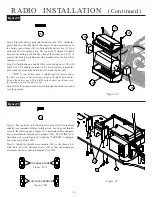
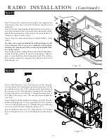
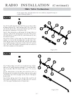
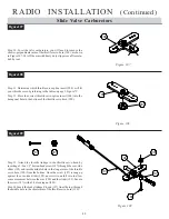
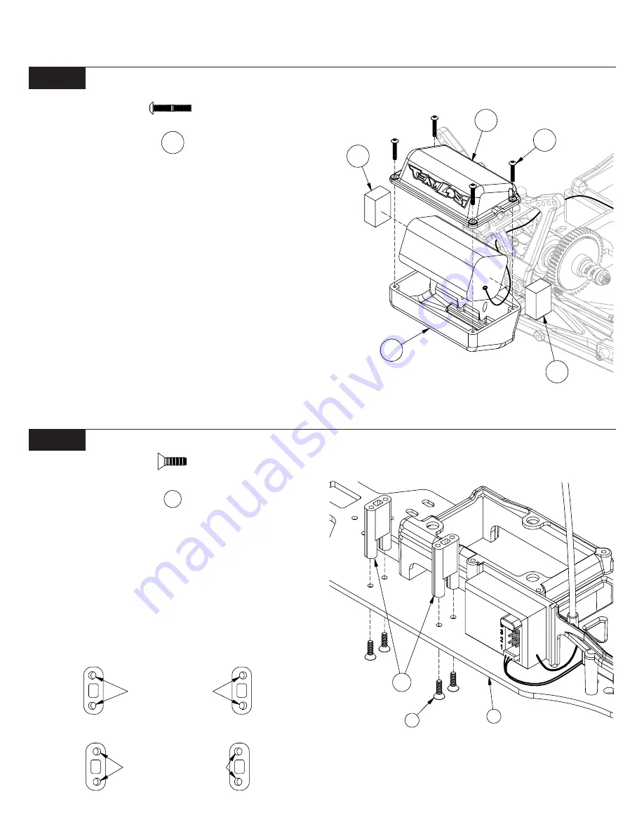
Figure 92
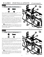
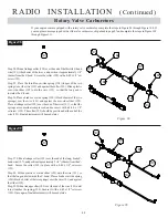
Figure 93
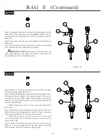
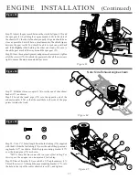
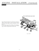
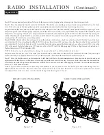
Step 11. The top holes in the throttle servo mounts (188) are offset
slightly to accomodate different width servos. Look up your throttle
servo in the table on page 3, Figure 7C to determine what configura-
tion to assemble the throttle servo mounts (188). The "WIDE" con-
figuration is shown in Figures 93A and the "NARROW" configura-
tion is shown in Figure 93B.
Step 12. Attach the throttle servo mounts (188) to the chassis (19)
with two 4-40 x 3/8" flat-head screws (20), so that the mounts are
oriented correctly, as shown in Figure93A or 93B.
TOP HOLES WIDE
TOP HOLES NARROW
Figure 93B
Figure 93A
125
185
187
186
185
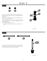
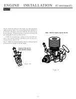
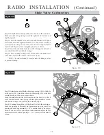
Step 8. Place the battery pack into the battery box (125), so that the
power lead is to the right side of the chassis. Cut two small pieces of
the battery spacer foam (185) to fit inside the battery box (125) on
each side of your battery pack. The foam (185) should fit tightly
between the battery pack and the sides of the battery box (125) to
prevent the battery pack from moving around inside the box while
running your truck.
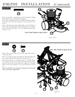
Step 9. Attach the battery box lid (186) to the battery box (125) with
four 2-56 x 1/2" button-head screws (187). Be carefull not to pinch the
power lead in between the battery box (125) and the lid (186).
*NOTE: If your battery pack is smaller and fits loosely under
the lid, cut a piece of battery spacer foam to fit tightly between the
lid and the battery pack. This will keep the battery pack from mov-
ing up and down in the battery box.
Step 10. Route the power lead forward through the shock tower and
over the gearbox.
Figure 92
187
20
188
19
Figure 93
20

