408- 1559
7
of 10
Rev
T
B. Gaging Crimping Chamber
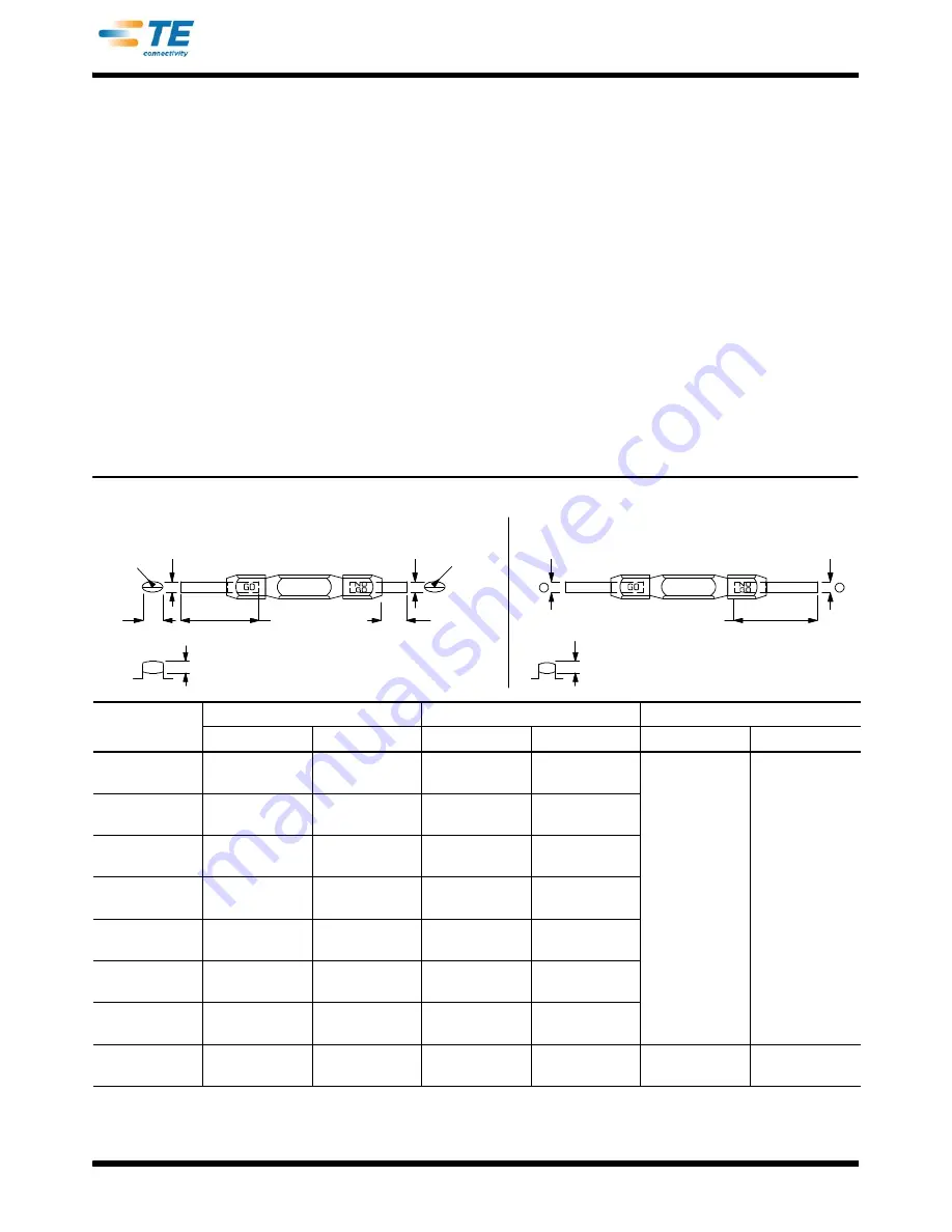
This inspection requires the use of plug gages
conforming to the dimensions listed in Figure 8. To
gage the crimping chamber, proceed as follows:
1. Close the jaws by squeezing the tool handles
together until the jaws have bottomed, and then
HOLD the handles in this position. DO NOT force
the jaws beyond initial contact.
2. Align the GO element of the gage with the wire
barrel crimp section of the crimping chamber. Refer
to Figure 9. Push the element straight into the
crimping chamber without using force. The GO
element must pass completely through the
crimping chamber.
3. Align the NO--GO element of the gage with the
same crimp section, and try to insert the element.
The NO--GO element may start entry, but it must
not pass completely through the crimping chamber.
Refer to Figure 9.
4. Repeat the gage inspection for the insulation
crimp section of the crimping chamber, making
sure to use the correct plug gage.
If the crimping chamber conforms to the gage
inspection, the tool is considered dimensionally
correct. If the crimping chamber does not conform to
the inspection, the tool must be repaired. Refer to
Section 6, REPLACEMENT AND REPAIR.
For additional information concerning the use of the
plug gage, refer to instruction sheet 408--7424.
C. Ratchet Inspection
Obtain a .025--mm [.001--in.] shim that is suitable for
checking the clearance between the bottoming
surfaces of the jaws. To inspect the ratchet control,
proceed as follows:
1. Refer to Figure 3, and select a product and
maximum size wire.
R
(Typ)
12.7 [.50]
Min Typ
31.75 [.125]
Min Typ
Tool 69454
Jaw Closure
Configuration
Jaw Closure
Configuration
50.8 [2.00]
Min Typ
Suggested Plug Gage Design — Wire Barrel Crimp Section
A
A
C
(Max)
B
(NO--GO)
B
(GO)
R
(Typ)
All Other Tools
B
(NO--GO)
B
(GO)
TOOL
JAW CLOSURE
{
DIAMETER A
GAGE ELEMENT
{{
DIAMETER B
DIMENSION
TOOL
GO
NO--GO
GO
NO--GO
C (Width)
R (Radius)
46121
--0
169485
--
1.600 [.0630]
1.753 [.0690]
1.600--1.608
[.0630--.0633]
1.750--1.753
[.0689--.0690]
47304
--0
1.600 [.0630]
1.753 [.0690]
1.600--1.608
[.0630--.0633]
1.750--1.753
[.0689--.0690]
47386
--0
47386--5
2.768 [.1090]
2.921 [.1150]
2.768--2.776
[.1090--.1093]
2.918--2.921
[.1149--.1150]
47387
68343--1
3.022 [.1190]
3.175 [.1250]
3.022--3.030
[.1190--.1193]
3.172--3.175
[.1249--.1250]
—
—
47907--1
2.260 [.0890]
2.413 [.0950]
2.260--2.268
[.0890--.0893]
2.410--2.413
[.0949--.0950]
48518--2
1.600 [.0630]
1.753 [.0690]
1.600--1.608
[.0630--.0633]
1.750--1.753
[.0689--.0690]
69151--1
2.768 [.1090]
2.921 [.1150]
2.768--2.776
[.1090--.1093]
2.918--2.921
[.1149--.1150]
69454
--0
2.616 [.1030]
2.718 [.1070]
2.616--2.624
[.1030--.1033]
2.715--2.718
[.1069--.1070]
3.962 [.156]
3.454 [.136]
Figure 8 (Cont’d)
{
Jaw closure dimensions apply when wire barrel jaws are bottomed, but not under pressure.
{{
Material: Tool Steel


