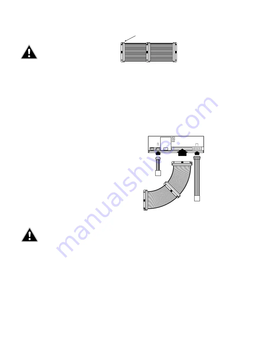
Figure 10:
Connecting the IDE Ribbon Cable
7.
Double-check your work. Make sure the side of the IDE cable with the red stripe is matched to Pin 1
on the interface board and on the drive.
Figure 11:
Power and IDE Connections for an Internal veloCD ReWRITER
8.
Connect a power cable from the computer to the DC INPUT connector of the veloCD ReWRITER.
In most computers, you will find free power connectors that are ready for your use.
Check the cable running from your power supply to your hard drive and see if it has extra connectors
on it. If so, you can plug one of these into the power connector found on the rear panel of the
veloCD ReWRITER.
9.
Connect the audio cable if you want to use a soundcard in your system. This cable runs from the
four pin audio output connector on the rear panel of your veloCD ReWRITER to your soundcard.
See "Using Soundcards and Audio Cables" below for more information about audio cables.
10.
Mount the veloCD ReWRITER in the computer using the four screws that were supplied with your
drive. Use only these screws.
12
veloCD ReWRITER :
User’s Manual
Connect any connector of the cable to the
motherboard or the veloCD ReWRITER.
Maximum cable length: 18 in.
PIN #1 (red wire)
IDE ribbon cable
Power cable
CD-ROM audio
connector on PC
Power supply
Internal veloCD ReWRITER
CAUTION:
It is easy to accidentally plug your IDE ribbon
cable upside down into both your drive and the mother-
board if your cable is not keyed. Be sure you match the
red stripe along one side of the IDE cable to Pin 1 on
the motherboard and Pin 1 on the drive. (Pin 1 on the
drive is closest to the power connector.) Each connector
on the ribbon cable has a "key" in the middle. This key
should fit into a slot in the middle of each connector of
the motherboard, your veloCD ReWRITER, and any other
internal IDE peripherals.
CAUTION:
Do not mount your drive in your computer
using screws other than those supplied by TDK.
You may damage the drive if you insert screws
that are too long.


