Maintenance, Service, and Repair
Page 3
Disc Brake Rotor
NOTE: The front brake rotor is an integral part of the front hub. If the brake rotor is worn beyond its
service limits, then the front hub must be replaced. Refer to
Front Axle Service
for information
on replacing the front hub.
Note: Depending on the rear axle configuration, the rear brake rotor may be an integral part of the rear
axle. If the brake rotor is worn beyond its service limits, then the rear axle must be replaced.
Refer to
Transmission
section for information regarding replacing the rear axle
Note: The wheel must be removed to accurately measure the rotor thickness. Refer to
Tires and
Wheels
section for information on removing the wheel.
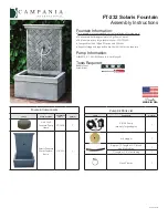
1. Measure the run out of the rotor at its maximum diameter. If the run out exceeds 0.005, then the rotor
must be machined. Do not machine the rotor beyond its service limits.
Note: A bent axle or damaged rear axle could cause excessive brake rotor run out.
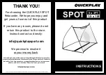
2. Measure the thickness of the brake rotor in 3 places. If the brake rotor thickness is less than 0.20-inches,
then the rotor must be replaced.
Do not use a rotor that is worn
beyond its service limits. A
rotor worn beyond its service
limits could fail and cause
loss of brakes resulting in
severe bodily injury and/or
property damage.
Current Taylor-Dunn
®
brakes are asbestos free. However, there is the
possibility that the original brakes were replaced with aftermarket
parts containing asbestos. Since this possibility exists, all brake parts
should be handled as if they contain asbestos. Refer to appendix C
for recommended handling precautions.
Rotor removed for clarity. The rotor does not
have to be removed for this procedure.
Summary of Contents for SC-100-24
Page 2: ......
Page 14: ...INTRODUCTION Page 8 Notes ...
Page 40: ...SAFETY RULES AND OPERATING INSTRUCTIONS Safety Rules Page 22 Notes ...
Page 46: ...Maintenance Service and Repair Front Axle Page 6 Notes ...
Page 65: ...TABLE OF CONTENTS Throttle Linkage Throttle Linkage Adjustments 2 Throttle Linkage ...
Page 81: ...Maintenance Service and Repair Page 9 Transmission view from rear ...
Page 93: ...Maintenance Service and Repair Page 21 NOTE Values shown are for reference only C D ...
Page 94: ...Maintenance Service and Repair Page 22 Notes ...
Page 100: ...Maintenance Service and Repair Page 6 Notes ...
Page 118: ...Wire Diagrams Wire Diagrams Page 2 Notes ...
Page 120: ...Illustrated Parts Page 2 Front Axle and Fork ...
Page 122: ...Illustrated Parts Page 4 Steering Linkage ...
Page 126: ...Illustrated Parts Page 8 Transmission Differential Case ...
Page 128: ...Illustrated Parts Page 10 Rear Axle ...
Page 130: ...Illustrated Parts Page 12 Rear Brakes ...
Page 132: ...Illustrated Parts Page 14 Motor ...
Page 134: ...Illustrated Parts Page 16 Brake Linkage ...
Page 136: ...Illustrated Parts Page 18 Throttle Linkage Slip joint detail ...
Page 138: ...Illustrated Parts Page 20 Wheels and Tires page 1 ...
Page 140: ...Illustrated Parts Page 22 Wheels and Tires page 2 ...
Page 144: ...Illustrated Parts Page 26 Speed Control Panel ...
Page 148: ...Illustrated Parts Page 30 Charger Lestronic Page 1 ...
Page 150: ...Illustrated Parts Page 32 Charger Lestronic Page 2 ...
Page 156: ...Illustrated Parts Page 38 Frame Seat Cushions and Deck Trailer Hitches ...
Page 158: ...Illustrated Parts Page 40 Decals ...
Page 160: ...Illustrated Parts Page 42 Knee Pad and Floor Mats optional ...
Page 162: ...Illustrated Parts Page 44 Lift Out Battery Box optional Illustration not available ...
Page 164: ...Illustrated Parts Page 46 Ladders and Strobe Light optional Strobe Light ...
Page 166: ...Illustrated Parts Page 48 Notes ...
Page 175: ......