Electrical Troubleshooting
Troubleshooting
Page 19
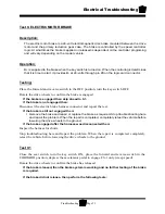
TEST 6.7:
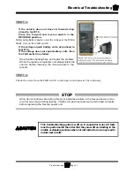
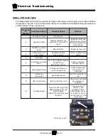
If the test at pin #4 on the 12-pin logic card connector failed, but the test at pin #5 at the
accelerator module was good (#6.5), then check the wire from pin #5 (module) to pin #4
(logic card).
If the test at pin #10 on the 12-pin logic card connector failed, but the test at pin #1 at
the accelerator module was good (#6.6), then check the wire from pin #1 (module) to pin
#10 (logic card).
Stop trouble shooting here and repair the problem. When the repair is completed, completely
retest the vehicle before lowering the drive wheels to the ground.
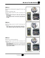
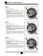
TEST 6.6:
Accelerator pedal depressed.
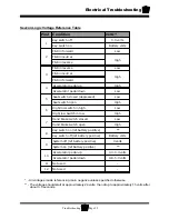
Test the voltage from pin #9 to pin #1.
If the voltage is between 4.8 and 5.1 volts, then
skip ahead to test #6.7.
If the voltage is not between 4.8 and 5.1 volts,
then the module has failed and must be replaced.
Stop trouble shooting here and repair the problem.
When the repair is completed, completely retest the
vehicle before lowering the drive wheels to the
ground.
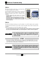
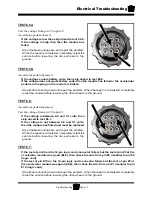
TEST 6.5a:
Test the voltage from pin #5 to pin #8.
Accelerator pedal released.
If the voltage is low then skip ahead to test 6.5b.
If the voltage is high then then the module has
failed.
Stop trouble shooting here and repair the problem.
When the repair is completed, completely retest the
vehicle before lowering the drive wheels to the
ground.
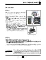
TEST 6.5b:
Accelerator pedal depressed.
If the voltage equals battery volts, then skip ahead to test #6.6.
If the voltage does not equal battery volts, then the module has failed or the accelerator
pedal return spring on the module is broken.
Stop trouble shooting here and repair the problem. When the repair is completed, completely
retest the vehicle before lowering the drive wheels to the ground.
Summary of Contents for MB-238-00
Page 2: ......
Page 6: ...TAYLOR DUNN...
Page 28: ...TAYLOR DUNN...
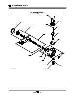
Page 44: ...Maintenance Service and Repair Steering Page 8 Exploded View of Steering Gear...
Page 64: ...TAYLOR DUNN...
Page 112: ...TAYLOR DUNN...
Page 149: ...TABLE OF CONTENTS Wire Diagrams Complete Vehicle 2...
Page 158: ...Illustrated Parts Parts Page 8 Transmission Gear Case...
Page 162: ...Illustrated Parts Parts Page 12 Rear Brakes Brake Body Assembly...
Page 166: ...Illustrated Parts Parts Page 16 Brake Lines Illustration not available...
Page 168: ...Illustrated Parts Parts Page 18 Motor...
Page 170: ...Illustrated Parts Parts Page 20 Wheels and Tires Ref wheel hub 1 2 3 Rear Suspension...
Page 172: ...Illustrated Parts Parts Page 22 Speed Control Panel Instrument Panel dash...
Page 182: ...Illustrated Parts Parts Page 32 Seat Cushions Deck and Lights Frame Illustration not available...
Page 184: ...Illustrated Parts Parts Page 34 Decals...


