Electrical Troubleshooting
Troubleshooting
Page 12
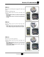
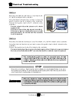
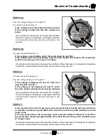
TEST 3.5
Disconnect the batteries and remove wires from the B-,
F1, and F2 terminals on the controller.
Using the diode test function on your meter, connect the
positive lead to the B- terminal on the controller.
Connect the negative lead to the F1 terminal on the
controller.
The test should show the presence of a diode
(approx 0.5v).
If the test is good, then skip ahead to test #3.6.
If the test is open or shorted then one or both
directional FET’s are shorted and the controller
must be replaced.
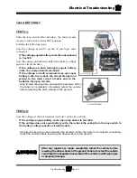
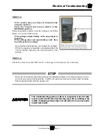
TEST 3.6
Disconnect the batteries and remove wires from the B-, F1, and F2 terminals on the controller.
Using the diode test function on your meter, connect the positive lead to the B- terminal on the
controller.
Connect the negative lead to the F2 terminal on the controller.
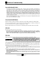
The test should show the presence of a diode (approx 0.5v). If the test is open or shorted
then one or both directional FET’s are shorted and the controller must be replaced.
After any repairs are made, completely retest the vehicle before
lowering the drive wheels to the ground. Failure to retest the vehicle
could result in unexpected movement of the vehicle resulting in injury
or property damage.
STOP
Stop, do not continue. Reaching this point indicates an unanticipated failure or an error
was made during testing. Confirm all previous tests were performed correctly and contact
your Taylor-Dunn
®
represetative for assistatnce.
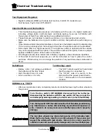
This troubleshooting guide is written in sequential order. All tests
must be performed in the order that they are written. Starting in the
middle or skipping sections when not instructed to do so may lead to
invalid test results.
Summary of Contents for MB-238-00
Page 2: ......
Page 6: ...TAYLOR DUNN...
Page 28: ...TAYLOR DUNN...
Page 44: ...Maintenance Service and Repair Steering Page 8 Exploded View of Steering Gear...
Page 64: ...TAYLOR DUNN...
Page 112: ...TAYLOR DUNN...
Page 149: ...TABLE OF CONTENTS Wire Diagrams Complete Vehicle 2...
Page 158: ...Illustrated Parts Parts Page 8 Transmission Gear Case...
Page 162: ...Illustrated Parts Parts Page 12 Rear Brakes Brake Body Assembly...
Page 166: ...Illustrated Parts Parts Page 16 Brake Lines Illustration not available...
Page 168: ...Illustrated Parts Parts Page 18 Motor...
Page 170: ...Illustrated Parts Parts Page 20 Wheels and Tires Ref wheel hub 1 2 3 Rear Suspension...
Page 172: ...Illustrated Parts Parts Page 22 Speed Control Panel Instrument Panel dash...
Page 182: ...Illustrated Parts Parts Page 32 Seat Cushions Deck and Lights Frame Illustration not available...
Page 184: ...Illustrated Parts Parts Page 34 Decals...

