


Maintenance, Service, and Repair
F2/F3 Transmission
Page 7
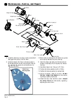
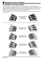
Assemble
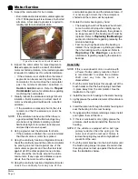
1. Thoroughly clean all gasket surfaces.
2. Apply a 1/8” bead of 94-430-03 gasket sealer to
the face of the 3rd member.
3. Install the backing plate to the 3rd member. Torque
to 30-45 ft-lbs.
4. Install the motor to the backing plate. Do not fully
tighten the motor mounting hardware at this time.
5. Install the motor sprocket, drive sprocket and
chain. Do not adjust the chain tension at this time.
6. Apply a 1/8” bead of 94-430-03 gasket sealer to
the chain case housing.
7. Install the chain case centering tool (refer to
Appendix A) into the pinion seal bore in the chain
case housing.
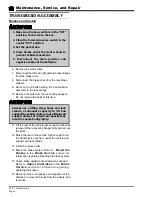
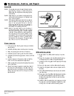
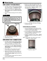
CHAIN CASE
NOTE: Some vehicle configurations may require that
the transmission be removed to disassemble
the chain case. Refer to section
Transmission Assembly
for information
on removing the transmission.
Disassemble
6. Place an oil drain pan under the chain case.
7. Remove the chain case drain plug and allow all of
the oil to drain from the housing and then reinstall
the drain plug
8. Remove the brake drum. Refer to section
Brakes: Replace the Brake Drum
for
information regarding removing the brake drum.
9. Remove the nuts from the three threaded studs at
the small end of the chain case housing.
10. Remove the chain case housing bolts, brake
assembly, and alignment brackets.
11. Remove the chain case housing from the backing
plate.
12. Remove the pinion seal from the chain case
housing.
13. Loosen the motor mounting bolts.
14. Loosen the chain adjuster.
15. Remove the drive chain, motor nut and sprocket
and the drive sprocket.
16. If the backing plate must be removed from the
3rd member, first remove the motor from the
backing plate then remove the backing plate from
the 3rd member.
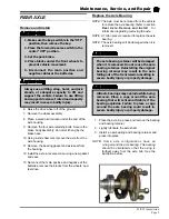
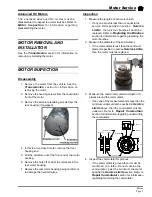
1. Make sure the key-switch is in the “OFF”
position, then remove the key.
2. Place the forward-reverse switch in the
center “OFF” position.
3. Set the park brake.
4. Place blocks under the front wheels to
prevent vehicle movement.
5. Disconnect the main positive and
negative cables at the batteries.
Typical Chain Case
Apply sealer around the ID of the holes
Summary of Contents for B0-012-10
Page 2: ......
Page 26: ...TAYLOR DUNN...
Page 53: ...Maintenance Service and Repair Steering Page 15 Exploded View of Steering Gear...
Page 54: ...TAYLOR DUNN...
Page 72: ...TAYLOR DUNN...
Page 85: ...Maintenance Service and Repair F2 F3 Transmission Page 13 EXPLODED VIEW...
Page 86: ...TAYLOR DUNN...
Page 94: ...TAYLOR DUNN...
Page 100: ...TAYLOR DUNN...
Page 106: ...TAYLOR DUNN...
Page 116: ...TAYLOR DUNN...
Page 172: ...Illustrated Parts Parts Page 2 Front Axle...
Page 176: ...Illustrated Parts Parts Page 6 STEERING...
Page 178: ...Illustrated Parts Parts Page 8 STEERING GEAR...
Page 180: ...Illustrated Parts Parts Page 10 PARK BRAKE...
Page 182: ...Illustrated Parts Parts Page 12 DEADMAN SEAT BRAKE optional...
Page 184: ...Illustrated Parts Parts Page 14 MASTER CYLINDER BRAKE LINKAGE...
Page 186: ...Illustrated Parts Parts Page 16 HYDRAULIC BRAKE LINES...
Page 188: ...Illustrated Parts Parts Page 18 FRONT BRAKES optional REAR BRAKES...
Page 195: ...Illustrated Parts Parts Page 25 This page intentionally left blank...
Page 202: ...Illustrated Parts Parts Page 32 POWER TRACTION DRIVE...
Page 204: ...Illustrated Parts Parts Page 34 REAR DIFFERENTIAL...
Page 208: ...Illustrated Parts Parts Page 38 Tires Wheels 10 Ref wheel hub 1 2 5 assembly 4 3 6 7 8 9...
Page 210: ...Illustrated Parts Parts Page 40 CONTROL PANEL...
Page 212: ...Illustrated Parts Parts Page 42 CONTROL PANEL EE...
Page 216: ...Illustrated Parts Parts Page 46 DECALS MISCELLANEOUS STANDARD PARTS...
Page 218: ...Illustrated Parts Parts Page 48 MISCELLANEOUS STANDARD PARTS Cont d...
Page 220: ...Illustrated Parts Parts Page 50 Options...
Page 222: ...Illustrated Parts Parts Page 52...
Page 224: ...Illustrated Parts Parts Page 54...
Page 226: ...Illustrated Parts Parts Page 56...
Page 228: ...Illustrated Parts Parts Page 58...
Page 230: ...Illustrated Parts Parts Page 60...
Page 232: ...Illustrated Parts Parts Page 62...
Page 234: ...Illustrated Parts Parts Page 64...
Page 238: ...Illustrated Parts Parts Page 68...
Page 244: ...Illustrated Parts Parts Page 74...
Page 246: ...TAYLOR DUNN...


