


Maintenance, Service, and Repair
Brakes
Page 9
NOTE: It is recommended that both the left and right
brake pads be replaced as a set.
NOTE: Installing new brake pads will raise the brake
fluid level in the master cylinder.
6. Thoroughly clean the area around the master
cylinder cap.
7. Remove fluid from the master cylinder until it is 1/
2 full.
8. Raise the rear of the vehicle and support with jack
stands.
9. Remove the tire/wheel assembly.
NOTE: Refer to
Tires and Wheels
section for
information on removing the tire and wheel
assembly.
10. Release the park brake (wheel brake only).
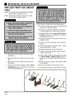
11. Remove the brake body bolts and discard the lock
nuts and brake pads.
12. Remove the spacer bushings from the mounting
bracket and discard.
13. Inspect the brake rotor. Refer to
Inspect the
Service Brake
section for information regarding
inspecting the brake rotor.
REPLACE REAR BRAKE PADS OR SHOES
Current Taylor-Dunn
®
brakes are asbestos
free. However, there is the possibility that
the original brakes were replaced with
aftermarket parts containing asbestos.
Since this possibility exists, all brake parts
should be handled as if they contain
asbestos. Refer to Appendix C for
recommended handling precautions.
1. Make sure the key-switch is in the “OFF”
position, then remove the key.
2. Place the forward-reverse switch in the
center “OFF” position.
3. Confirm the electric park brake is set.
4. Place blocks under the front wheels to
prevent vehicle movement.
5. Disconnect the main positive and
negative cables at the batteries.
Always use a lifting strap, hoist, and jack
stands, of adequate capacity to lift and
support the vehicle. Failure to use lifting
and support devices of rated load capacity
may result in severe bodily injury.
14. Inspect the spacers and replace if any wear or
damage is found.
15. Install new spacer bushings in the mounting
bracket.
16. Back off the parking brake adjustment (wheel park
brake only).
17. Install new brake pads in reverse order. Torque
the mounting bolts to 11 ft-lbs.
18. Repeat this procedure for the other wheel.
19. Install the tire/wheel assembly and lower the
vehicle to the ground.
20. Fill the master cylinder to the proper level. Refer
to
Check Master Cylinder Fluid
section for
information regarding the correct master cylinder
fluid level.
21. Adjust the parking brake (wheel park brake only).
Refer to
Adjust the Parking Brake
section.
22. Set the park brake.
23. Reconnect the main positive and negative cables
at the batteries.
24. Remove the blocks from behind the wheels.
25. Release the park brake and test drive the vehicle.
Summary of Contents for B0-012-10
Page 2: ......
Page 26: ...TAYLOR DUNN...
Page 53: ...Maintenance Service and Repair Steering Page 15 Exploded View of Steering Gear...
Page 54: ...TAYLOR DUNN...
Page 72: ...TAYLOR DUNN...
Page 85: ...Maintenance Service and Repair F2 F3 Transmission Page 13 EXPLODED VIEW...
Page 86: ...TAYLOR DUNN...
Page 94: ...TAYLOR DUNN...
Page 100: ...TAYLOR DUNN...
Page 106: ...TAYLOR DUNN...
Page 116: ...TAYLOR DUNN...
Page 172: ...Illustrated Parts Parts Page 2 Front Axle...
Page 176: ...Illustrated Parts Parts Page 6 STEERING...
Page 178: ...Illustrated Parts Parts Page 8 STEERING GEAR...
Page 180: ...Illustrated Parts Parts Page 10 PARK BRAKE...
Page 182: ...Illustrated Parts Parts Page 12 DEADMAN SEAT BRAKE optional...
Page 184: ...Illustrated Parts Parts Page 14 MASTER CYLINDER BRAKE LINKAGE...
Page 186: ...Illustrated Parts Parts Page 16 HYDRAULIC BRAKE LINES...
Page 188: ...Illustrated Parts Parts Page 18 FRONT BRAKES optional REAR BRAKES...
Page 195: ...Illustrated Parts Parts Page 25 This page intentionally left blank...
Page 202: ...Illustrated Parts Parts Page 32 POWER TRACTION DRIVE...
Page 204: ...Illustrated Parts Parts Page 34 REAR DIFFERENTIAL...
Page 208: ...Illustrated Parts Parts Page 38 Tires Wheels 10 Ref wheel hub 1 2 5 assembly 4 3 6 7 8 9...
Page 210: ...Illustrated Parts Parts Page 40 CONTROL PANEL...
Page 212: ...Illustrated Parts Parts Page 42 CONTROL PANEL EE...
Page 216: ...Illustrated Parts Parts Page 46 DECALS MISCELLANEOUS STANDARD PARTS...
Page 218: ...Illustrated Parts Parts Page 48 MISCELLANEOUS STANDARD PARTS Cont d...
Page 220: ...Illustrated Parts Parts Page 50 Options...
Page 222: ...Illustrated Parts Parts Page 52...
Page 224: ...Illustrated Parts Parts Page 54...
Page 226: ...Illustrated Parts Parts Page 56...
Page 228: ...Illustrated Parts Parts Page 58...
Page 230: ...Illustrated Parts Parts Page 60...
Page 232: ...Illustrated Parts Parts Page 62...
Page 234: ...Illustrated Parts Parts Page 64...
Page 238: ...Illustrated Parts Parts Page 68...
Page 244: ...Illustrated Parts Parts Page 74...
Page 246: ...TAYLOR DUNN...


