


Electrical Troubleshooting
Signet Charger Troubleshooting
Page 3
OPERATING INSTRUCTIONS AND THEORY OF OPERATION
The model HBS 600W
®
and HBS 1000W
®
chargers are designed as automatic chargers. The charger turns
itself on when it is plugged into the wall outlet and turns off when the batteries are fully charged. Once the
charging cycle is complete, the charger will monitor the battery voltage. If the battery voltage drops below a
specific value (V2), the charger will turn on again for a short cycle.
Both the HBS 600W
®
and HBS 1000W
®
are two stage chargers. The first stage is a constant current mode. It
Maintains a constant current until the battery reaches a terminal voltage (V1) and then switches to the second
stage, constant voltage. At the second stage the charger decreases the charger current while holding the
batteries at the terminal voltage until the charging cycle is complete. The charging cycle is complete when the
current is down to A1
On the charger face plate, there is a status light panel that displays the current status of the charger.
The first light (
POWER
) should be ON when the AC cord is connected to a proper AC power source.
The three
STATUS
lights will indicate the current charging condition as follows:
Left:
Charge cycle is ON and is in constant current mode.
Left & Middle (80%):
Charge cycle is ON and is in constant voltage mode.
Right (100%):
Charge cycle completed.
The
FAULT
light will turn ON and flash a fault code only when an abnormal charging condition has occurred.
Refer to the fault code table for more information.
NOTE: Critical faults will be accompanied with an audible beeping.
Typical specification plate
(reference only, specifications will vary for different chargers)
Summary of Contents for B0-012-10
Page 2: ......
Page 26: ...TAYLOR DUNN...
Page 53: ...Maintenance Service and Repair Steering Page 15 Exploded View of Steering Gear...
Page 54: ...TAYLOR DUNN...
Page 72: ...TAYLOR DUNN...
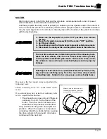
Page 85: ...Maintenance Service and Repair F2 F3 Transmission Page 13 EXPLODED VIEW...
Page 86: ...TAYLOR DUNN...
Page 94: ...TAYLOR DUNN...
Page 100: ...TAYLOR DUNN...
Page 106: ...TAYLOR DUNN...
Page 116: ...TAYLOR DUNN...
Page 172: ...Illustrated Parts Parts Page 2 Front Axle...
Page 176: ...Illustrated Parts Parts Page 6 STEERING...
Page 178: ...Illustrated Parts Parts Page 8 STEERING GEAR...
Page 180: ...Illustrated Parts Parts Page 10 PARK BRAKE...
Page 182: ...Illustrated Parts Parts Page 12 DEADMAN SEAT BRAKE optional...
Page 184: ...Illustrated Parts Parts Page 14 MASTER CYLINDER BRAKE LINKAGE...
Page 186: ...Illustrated Parts Parts Page 16 HYDRAULIC BRAKE LINES...
Page 188: ...Illustrated Parts Parts Page 18 FRONT BRAKES optional REAR BRAKES...
Page 195: ...Illustrated Parts Parts Page 25 This page intentionally left blank...
Page 202: ...Illustrated Parts Parts Page 32 POWER TRACTION DRIVE...
Page 204: ...Illustrated Parts Parts Page 34 REAR DIFFERENTIAL...
Page 208: ...Illustrated Parts Parts Page 38 Tires Wheels 10 Ref wheel hub 1 2 5 assembly 4 3 6 7 8 9...
Page 210: ...Illustrated Parts Parts Page 40 CONTROL PANEL...
Page 212: ...Illustrated Parts Parts Page 42 CONTROL PANEL EE...
Page 216: ...Illustrated Parts Parts Page 46 DECALS MISCELLANEOUS STANDARD PARTS...
Page 218: ...Illustrated Parts Parts Page 48 MISCELLANEOUS STANDARD PARTS Cont d...
Page 220: ...Illustrated Parts Parts Page 50 Options...
Page 222: ...Illustrated Parts Parts Page 52...
Page 224: ...Illustrated Parts Parts Page 54...
Page 226: ...Illustrated Parts Parts Page 56...
Page 228: ...Illustrated Parts Parts Page 58...
Page 230: ...Illustrated Parts Parts Page 60...
Page 232: ...Illustrated Parts Parts Page 62...
Page 234: ...Illustrated Parts Parts Page 64...
Page 238: ...Illustrated Parts Parts Page 68...
Page 244: ...Illustrated Parts Parts Page 74...
Page 246: ...TAYLOR DUNN...