background image

2nd- (Front-) Tractor (option)

10-1

10

2nd- (Front-) Tractor (option)

Summary of Contents for 2365

Page 1: ...Maintenance manual Matrix printer 2365 2380...

Page 2: ...This page intentionally left blank...

Page 3: ...nctions 3 3 3 2 1 Head PlatenClearance 3 3 3 2 2 Shift Friction Tractor 3 5 3 2 3 Monitoring Light Barrier PathSelection 3 10 3 2 4 Position of the Wheels 3 11 3 2 5 Paperways 3 13 3 3 Electronic Func...

Page 4: ...3 23 Additional fonts 3 36 3 3 23 1 Non scalable fonts 3 36 3 3 23 2 Scalable fonts 3 39 3 3 23 3 Barcodes 3 41 3 3 24 Theory of Adjusting Printhead Temperature 3 42 Chapter 4 Testmodes and Troublesh...

Page 5: ...5 Replacing the Automatic Width Sensor APW 5 13 5 3 6 Replacing Carriage Adapter 5 14 5 3 7 Replacing Connector Board 5 16 5 4 Replacing Motors 5 17 5 4 1 Replacing Carriage DC Motor 5 17 5 4 2 Repla...

Page 6: ...rent Loop Option 048957 6 9 6 2 1 3 Interface RS422 Option 048956 6 10 6 3 Soft Adjustments 6 11 6 3 1 Setting of Head Temperature NDK9 Reference value 6 11 6 3 2 Adjustment of AGA 6 12 Chapter 7 Spar...

Page 7: ...Option 7 26 7 12 1 1 Connector assignment 7 26 7 12 1 2 Interface cable serial interface 7 27 7 12 1 3 Input signals 7 27 7 12 1 4 Output signals 7 27 Chapter 8 Rear Tractor 2T Model 8 1 8 1 Specifica...

Page 8: ...This page intentionally left blank...

Page 9: ...ce All elements of the printer control are arranged on printed circuit boards so that only a few additional components are required such as step motor for function select step motor for paper feed DC...

Page 10: ...This page intentionally left blank...

Page 11: ...0 533 10 0 12 x 12 720 800 720 12 0 12 x 10 900 1000 900 15 0 08 x 08 900 1000 900 15 0 12 x 08 515 571 515 17 1 12 x 12 600 667 600 20 0 12 x 10 CPQ Copy Print Quality 300 333 270 10 0 24 x 12 360 40...

Page 12: ...on Roman T Sans Serif H DLL is standard but not battery buffered Large Character Printing LCP A 2 5 Matrix default B 2 5 Industrial C 2 5 Interleaved D Code 11 E BCD Matrix F Code 39 G Codabar H EAN 8...

Page 13: ...actor 2 front Tractor 2 front Tractor 2 front Service life Printhead Ribbon 2365 2380 2365MC 750 millions 750 millions 500 millions DPQ DPQ DPQ 12 x 12 matrix 12 x 12 matrix 12 x 12 matrix 20 million...

Page 14: ...EnergyStar Dimensions Width Height Depth 624 mm 24 57 inches 280 mm 11 02 inches 432 mm 17 01 inches Environmental conditions Operation Temperature Rel humidity Climate Storage Temperature Rel humidit...

Page 15: ...Std 1284 1294 Voltage supply of exter nal devices on pin 18 U 5 V 10 I 0 5 Amax Interface connections Printer side Amphenol 57 40360 36 pin or compatible Cable side Amphenol 57 30360 25 pin or compat...

Page 16: ...tion cable Interface connections Transmission protocol Capacity of data buffer Option RS232C interface Asynchronous 600 bauds to 19 200 bauds OFF Mark log 1 3 V to 15 V ON Space log 0 3 V to 15 V Leng...

Page 17: ...s paper single part forms tractor 3 2T model only Weight Width Form length 60 to 90 g m2 76 to 406 mm 76 to 559 mm Continuous paper multi part forms tractor 3 to be tested individually 2T model only C...

Page 18: ...papers Since paper as natural material reacts strongly to environmental influences e g humidity tempera ture the place of storage should be selected care fully We recommend that this kind of paper sho...

Page 19: ...in 406 406 front front buttom buttom rear rear side side line d imensioning line dimensioning centre of foot centre of foot all dimensions all dimensions in mm in mm M 1 5 M 1 5 1 5 1 5 paper way in...

Page 20: ...This page intentionally left blank...

Page 21: ...tched by the user externally from 120 V to 230 V A fuse T4 00AH250V UL is provided to protect the power supply from hazardous damages It can be replaced without opening the printer 3 1 3 Ribbon The qu...

Page 22: ...0 The address of the router or gateway is 0 0 0 0 if not available 3 1 4 1 Example of a printer connected to a computer in an Ethernet 3 1 4 2 Example of several de vices in an Ethernet 3 1 5 Monitori...

Page 23: ...er the head distance stepper moves the toothed segment on block at the worm gear Now the printer has its basic point and can count the steps forward which are stored in the firmware The stepper tolera...

Page 24: ...Mechanical Functions Functional Description 3 4 Mechanic Rotation Platen Mean point carriage axle Bearing point ca 1 4 mm Movement of Carriage 26...

Page 25: ...nction Select Description Explosion view function unit Toothing Connects tractor wheels and turret in engaged state if not engaged the tractor wheels are free running on the turret Tractor wheel 1 Tra...

Page 26: ...d in the position of the guide line 5 To lock into position tractor 2 the switching gear is not turned back Then the revolving sleeve is not locked in the turret but locked in the sliding sleeve Base...

Page 27: ...d in intermediate position Tractor wheel 1 and revolving sleeve are not locked in the turret Revolving Sleeve Turret Tractor 1 Gear wheel Position 2 according position 1 however revolving sleeve engag...

Page 28: ...hrough the tractor wheels idling Power transmission per drive to the vice versa side Tractor wheel 1 is not toothed in the turret and tractor wheel 2 is not locked in the gear wheel Revolving Sleeve T...

Page 29: ...tor wheel 1 tractor wheel 2 gear wheel tractor 2 Revolving Sleeve Turret Tractor 1 Gear wheel Lock position Power transmission Tractor 2 Drive Tractor wheel 2 Tractor wheel 1 Sliding Sleeve Switching...

Page 30: ...Mechanical Functions Functional Description 3 10 3 2 3 Monitoring Light Barrier PathSelection FSS1 FSS2 Description 0 5 Tractor 1 front 5 0 Tractor 2 optional front 5 5 Tractor 3 Rear Values in Volt...

Page 31: ...and eccenters have to be mounted in the correct positions marks There are several marks on both side walls and the corresponding wheels and dampers See the following drawing for further details For co...

Page 32: ...Mechanical Functions Functional Description 3 12 right mark mark mark...

Page 33: ...Functional Description Mechanical Functions 3 13 3 2 5 Paperways Standard Printer 1st Tractor 1st Tractor Standard Printer 3rd Tractor Optional 3rd Tractor...

Page 34: ...rip 4 Interlock Sensor 5 Sensor Paper Position Front Insertion 6 Sensor Rear Tractor 7 Motor Driver Boards 8 Carriage Motor 9 Paper Motor 10 Paper Thickness Motor 11 Function Select Motor 12 Paper Thi...

Page 35: ...Functional Description Electronic Functions 3 15 2365 2380 Electronic groups...

Page 36: ...tching Power Supply To switch over from e g 120 V to 230 V the user only has to move the power selection bar To avoid unexpected switching you have to use a tool like tweezers to switch over The power...

Page 37: ...ist mainly of registers latches and selective logic 3 3 1 3 Needle Driver The needle driver signals NOxx are connected to the printhead via plug X14 X2 of the connection board to the printhead adapter...

Page 38: ...3 3 2 Panel The panel consists of 2 Function Keys Online Setup and 4 situation dependent softkeys It will be plugged in via x6 connection board Online Trac1 Tear Online Setup 2 1 3 4 10 9 8 7 6 5 4 2...

Page 39: ...the 8 standard data lines now in the opposite direction printer PC 2 1 Phase 1 Negotiation phase Procedure The PC sets SELECTIN to high and at the same time AUTOFEED to low The printer reacts within 3...

Page 40: ...s long as there are data to be transmitted the printer sets now PAPEREND ERROR SELECT and BUSY to low and DONE once more to high The acknowledge of the PC is performed by setting AUTOFEED to low Now t...

Page 41: ...Main Board X5 Input Output wired to GND with 1nF GND GND IF3 GND VCC IF4 GND GND IF5 GND C12 B12 A12 C11 B11 A11 C10 A10 B10 C9 B9 A9 C8 B8 VCC IF6 GND DONEN READYN RTSN BUSY GND DTRN IF0 GND STRBN I...

Page 42: ...on the main board so that only the plugged in modular parallel I O s shall be active in order to avoid misreading data on the parallel data lines Two parallel I O s will not work together To avoid thi...

Page 43: ...ts If incoming data is on the other interface and the current print position is not Top of Form a form feed is carried out If shared parallel or shared serial is set all other interfaces are disabled...

Page 44: ...the RJ 45 connector on the rear panel Right green light is blinking Shows network activity Left yellow light Duplex Status is solid Shows network interface is in full duplex Left yellow light Duplex S...

Page 45: ...he TTL signals on the microprocessor side to the level of the current loop without any galvanical contact Received signals on the Rx loop should be changed by the optocoupler IC2 from current loop lev...

Page 46: ...ils SS97 The interface signals generated in the microprocessor and in the application s specified IC are connected to the driver IC1 This IC converts the TTL signals on the microprocessor side to the...

Page 47: ...ls about this board you will find in chapter 7 5 and 7 11 A fuse for UN is built in 5AT Slow Blow 3 3 4 1 Connection Board 2365 2380 AGA Option Sensor Color Motor Panel Logic Function Select Ribbon Mo...

Page 48: ...gnals are connected to X7 on the connector board For standard assembly only a 4 pin 1 4 connector is mounted 3 3 8 SensorSheetfeeder and 3rd Tractor This reflex sensor GP 2 S 7 is necessary for recogn...

Page 49: ...b r e v i r D t u o d r o B r o t c e n n o C Color Motor Sheetfeeder Motor Cutting Device Principle of stepper motor control Schematic Half Step motor principle Remark In the picture above a full ste...

Page 50: ...motor via plug X11 on the connector board 3 3 12 Sheetfeeder Motor Option This motor is located in the Gear Box and controlled by a Motor Driver Board By mounting the gear block is directly connected...

Page 51: ...e versa It is controlled by IC26 L 6219 on the main board The motor is plugged directly in X4 on the connection board Remark For testing it s possible to exchange the SF Motor 3 2 16 Paper Thickness M...

Page 52: ...ck Station Clock Pulses Test Gate Signals Main Friction Roll Thickness Test Mask Light Barrier 1 Light Barrier 2 of Clock Station Clock Band Test Gate Signals Clock Pulses T 2045 AGA PRINCIPLE Figure...

Page 53: ...ect Sensor This sensor monitors the position of the function select gears It is connected to X3 of Interconnection Board 10 9 8 7 6 5 4 2 3 1 UNX UNX GND CC1 SF3 X16 12 11 PGNG PGND TRR SF2 SF1 TRSB V...

Page 54: ...ement Option Monitors whether Paper is inserted to be fed in automatically Is to be plugged into X13 of Interconnection Board 3 3 21 Ribbon Motion Sensor Monitors whether the Ribbon is inserted correc...

Page 55: ...en replacing printhead Printhead The printer is equipped with a new designed printhead NDK9 This printhead contains an EEPROM printhead chip This EEPROM stores the calibration settings of the coils fo...

Page 56: ...41 X X X X X X X X X X X X X French 52 X X X X X X X X X X X X X German 4B X X X X X X X X X X X X X Italian 59 X X X X X X X X X X X X X Swedish 48 X X X X X X X X X X X X X Norwegian 60 X X X X X X...

Page 57: ...ended 95 1 1 1 Table 865 86 X X X X X X X X X X X X X Table 866 8E X X X X X 866 Bulgaria 9D X X X X X Siemens Turk 9B X X X X X DEC Turkish 9C X X X X X Table 125 70 X X X X X Table 1251 71 X X X X X...

Page 58: ...X 2 3 4 Old Code 860 98 X X X X X 2 3 4 Flarro 863 99 X X X X X 2 3 4 865 Hebrew 9A X X X X X 2 3 4 CP775 Baltic A6 X X X X X CP1257 Baltic 77 X X X X X Mazovia Poland 92 X X X X X Kamenicky Czech 91...

Page 59: ...ance X X X X Epson Germany X X X X X X X X K U n o s p E Epson Denmark X X X X Epson Sweden X X X X X X X X y l a t I n o s p E Epson Spain I X X X X Epson Japan X X X X Epson Norway X X X X Epson Den...

Page 60: ...Nordic X X X X CP866 Cyrillic Siemens Turkish DEC Turkish CP1250 Win Latin 2 CP1251 Win Cyrillic CP1252 Win Latin 1 CP1253 Win Greek CP1254 Win Turkish 8859 1 Latin 1 X X X X 8859 1 Latin 1 SAP 8859...

Page 61: ...EAN 8 without clear text line 10 Code EAN 13 with HRI 11 Code EAN 13 without HRI 12 Code MSI modified PLESSEY 13 Code UPC A with HRI 14 Code UPC A without HRI 15 Code UPC E with HRI 16 Code UPC E wit...

Page 62: ...istance The resi stance is measured continuously Therefore it is possible to monitor the printhead for highest performance but to protect it in case of overheating This control system must be adjusted...

Page 63: ...des and Troubleshooting The following internal printer tests are available ASCII tree 8 Inch ASCII tree 13 6 Inch Hex Dump capability Monitoring function For better understanding it is recommended to...

Page 64: ...djustment functions and special settings which are described in the in the User Guide as well ASCII80 ASCII136 W Single does not apply to this printer Setting for printing on paper with dark back W Se...

Page 65: ...the interface test hex dump you can check data transfer from computer to printer The text which is being transmitted to the printer is printed in two parts In the left part the text is printed in hexa...

Page 66: ...Top of Form TOF Disable the AED sensor Buffer Overflow Received data which have not yet been printed is overwrit ten from new data Check If the correct replay signal e g X ON X OFF is set in the menu...

Page 67: ...hether the printhead is blocked by an object e g by jammed paper or if the printhead distance is too small Try and remove the error by turning the printer off and then on again If this does not help c...

Page 68: ...y are the same Check whether the cable length and insulation of the interface cable corre sponds to the specifications To clear the error message you must switch of your printer Power Fail Internal so...

Page 69: ...ting head and or main logic Also adjust printhead only in cold state If you re manipulating the printhead i e plug unplug the head to solve a contact problem run the adjustment procedure to asure prop...

Page 70: ...way is loaded after installing different or new firmware Only Available in EPSON Mode Functions which are not meaningfull in this emulation have been selected To use the selected feature you have to s...

Page 71: ...her interface cable The interface configuration in your application pro gram is incorrect Set CX BID to OFF in menu Try modular MT350 360 380 Interface module Problem with the paper feed Select the co...

Page 72: ...nstall ribbon correctly correct fitting Check the thickness of the used paper inhomoge neous Use built in characters rather than TrueType Decrease resolution eg 180x180 dpi The printhead stops dur ing...

Page 73: ...ith the internal Ether net interface ETH INT Check if a proper interface cable is used Cat 5e 100 MHz Check if the connected switch or hub is set like the printers interface e g Switch Printer 100 MHz...

Page 74: ...Check paper guides Tractor1 Check AGA Check function motor No printout Defective printout Defective interface Check interface Check cable IEEE 1284 nibble mode Check external box speed Wrong interfac...

Page 75: ...OK Problem solved 1 Assure the ribbon fits for this printer model as the genuine has a code wheel Replace ribbon OK YES NO Use a genuine ribbon 1 OK YES NO Check for newest Firmware OK YES NO Check or...

Page 76: ...2 Adjustprinthead Temperature Calibration Star Appears a Star after m Print NO YES Let printer cool down use rather draft or copy draft than NLQ or LQ use lower graphic density refit printhead 1 Prin...

Page 77: ...lem solved green LED Flashing YES NO Replace Main Controller OK Change switch potentially install Hub OK YES NO END YES NO Trace Data 4 YES NO YES NO YES NO NO YES ETH INT Internal Interface Problem p...

Page 78: ...ter print in normal or visible reduced speed 1 Refitprinthead 2 3 times in order to overcome contact problems OK Problem solved Print NO YES Slow Re calibrate printhead Print NO YES Replace Main Contr...

Page 79: ...nded only temporarily Fits printout on paper Adapt printout driver NO YES preprinted logo YES NO use different paper OR Set different TOF Shift paper slightly to the left OK YES NO Replace APW Sensor...

Page 80: ...tion switched on or not In case of AGA On the actual relative value is displayed in case of AGA Off the manual set value is constantly displayed The current value of printhead temperature is shown onl...

Page 81: ...current horizontal position i e 680 AGA Flag lies in between 0 left phys left margin and approx 1730 right phys margin at position 337 00680 008N 1080 0 377 Tear Head platen gap 18 steps Default witho...

Page 82: ...he printer will test if a ribbon exists and during printing the motion of the ribbon is permanently checked If no ribbon is detected which is also the case when you use other ribbons or the ribbon is...

Page 83: ...the printer with a soft fluff free cloth Special printer bar cleaner can be purchased in specialised shops Remove all dust and paper residues from the printer mechanism using a brush Lubrication A Th...

Page 84: ...Reference resistor wrong or missing or contact failure Bit 4 1 xxx 008 Eeprom values wrong calibrating of printhead not ok Eeprom defect Thermo ASIC defect Above mentioned failure possibilities might...

Page 85: ...g the keys Online Setup during power on you can print out the con tents of the printhead chip The first two values of one line are the coil parameters in mV and m as before If a parameter is out of to...

Page 86: ...d Clearance B Task Control Code C Head Temperature D Actual Head Position E Horizontal Position of AGA Flag F Desired Head Position 3 Legend Actual Position Horizontal position of the printhead while...

Page 87: ...hift the horizontal drive belt one notch to the right and fasten belt again according adjustments 6 1 1 active 256 Paper Feed Sheetfeeder active 512 Bell sound active 1024 Shiftmagnet Printhead active...

Page 88: ...r light barrier Missing clocks from timing strip intermit tent printout is moving horizontally until carriage blocks on any side panel substitute head adapter cable replace it with level C substitute...

Page 89: ...ng danger of injury Open Top Cover Install the magnet at the interlock hall sensor on the left side wall by means of an adhesive tape Attention It is necessary to install the magnet with south pole in...

Page 90: ...keys 1 4 and Online Hold the keys pressed 3 Switch on your printer The printer is ready for the download when BOOT appears on its display 4 Copy the file e g DOWNLOAD FDF from the diskette A to your...

Page 91: ...d via FTP Put the printer into boot mode by pressing the keys 1 4 and Setup while switching the printer on Unpack the archive containing the firmware Open a DOS prompt in the directory where you have...

Page 92: ...trol soft ware and the character generators Make sure that blank paper is inserted in the valid paper source Keep the key 4 depressed for approx 5 seconds while turning on the printer After completion...

Page 93: ...053 528 Phillips screwdriver medium Screwdriver small TORX screwdriver 20 Grease Molycote white Longterm W2 1 Normally assembling is done vice versa of disassembling Caution Switch off the printer wai...

Page 94: ...acing Casing Instructions for Disassembly and Assembly 5 2 5 1 Replacing Casing 5 1 1 Replacing Top Case Remove Top Cover A and Rear Cover B 5 1 2 Replace Front Cover Lift Front Cover A to 90 degrees...

Page 95: ...s for Disassembly and Assembly Replacing Casing 5 3 Grab the snap fit from outer side and pull top front blind in technicians direction Lower the front cover and tilt the top front blind to 90 degrees...

Page 96: ...isassembly and Assembly 5 4 Lift the top front blind on the left hand side upwards and remove it If necessary use a screwdriver for support Use a screwdriver to unlock the left casing aperture as show...

Page 97: ...ht casing aperture as shown in the illustration and remove it Lift Front Cover out of Upper Housing and remove it Caution Be carefull while doing this step You may damage the panel cable A Caution Tak...

Page 98: ...ock the upper casing as shown in the illustration lift it upward and remove it Assembly For reassembling the Top Case run the procedure backwards Use a screwdriver to make sure that the snap lock on t...

Page 99: ...lacing Casing 5 7 5 1 3 Replacing Bottom Case For first steps see section 5 1 1 Disconnect Panel Caution Panel Cable is held by a plastic latch Remove optional Interface Board if present see section 5...

Page 100: ...Casing Instructions for Disassembly and Assembly 5 8 Release the 4 rubber snaps B C Hook 395 850 Remove Screws 4 x D Lift the printer mechanic with both hands straight upward and put it on a stable pl...

Page 101: ...Instructions for Disassembly and Assembly Printhead 5 9 5 2 Printhead 5 2 1 Removing the Printhead Remove the top cover Lift upper friction Unlock the screws A at the printhead A...

Page 102: ...the head connector fits correctly Lock the printhead C NDK9 only see chapter 4 11 to recognize the installed printhead After installing printhead you can calibrate the temperature of the head For fur...

Page 103: ...g Electronic Parts 5 3 1 Replacing Optional Interface Push lever A in right direction view from the rear Take the Interface cover and pull it in left direction B Attention Do not buckle the spring ins...

Page 104: ...nd 5 3 2 Remove Top Case see section 5 1 1 Turn the lock A on the back of the printer indicated by the arrow Pull slightly the board half out of the Bottom Case Disconnect Mains Voltage connector B Re...

Page 105: ...he hooks C outwards AGA Automatic Gap Adjustment 5 3 5 Replacing the Automatic Width Sensor APW Remove Holder A Open Strain Relief Clamp B and unplug Sensor cable C Remove Sensor from Paper Guide This...

Page 106: ...g section 5 1 1 Remove Main Board 5 3 3 and Lower Housing 5 1 2 Remove printhead as described in section 5 2 Remove Timing Strip carefully section 5 12 Remove all connected cables AGA Fan Encoder A Re...

Page 107: ...the given Cable guide B front and cable holder C back Unlock the two printhead cables D on the connection board by releasing the two strain relief clamps Pull them through the hole in the left side p...

Page 108: ...ector Board Remove Top Case section 5 1 1 Remove Main Board section 5 3 3 Remove Bottom Case section 5 1 2 Disconnect all plugs on the Board Attention Make sure to plug in the cables in the correct ma...

Page 109: ...1 Replacing Carriage DC Motor Remove Top and Bottom Case as seen in section 5 1 Release the tension of the horizontal belt by turning the tightener in upward direction A Unlock both screws B Disconnec...

Page 110: ...sembly 5 18 5 4 2 Replacing Stepper Motors Remove all necessary parts in order to access the desired side panel Unplug desired motor from Interconnection Board 5 3 7 Remove all screws If there are no...

Page 111: ...and Assembly Replacing Motors 5 19 5 4 3 Replacing Vertical Stepper LF Motor Remove Top and Bottom Case as described in section 5 1 Unplug vertical stepper from the connector board Unlock screw A Turn...

Page 112: ...sor Parts 5 5 1 Replacing Double Sensor Front Insertion Paper Position and Paper Motion Sensor Remove upper part of Casing section 5 1 Remove upper friction section 5 9 Remove carriage system section...

Page 113: ...Assembly Replacing Sensor Parts 5 21 5 5 2 Replacing Sheetfeeder Sensor Remove Optional Interface section 5 3 1 Remove Main Board section 5 3 2 Remove Housing section 5 1 Remove Sensor A at the bottom...

Page 114: ...e Housing section 5 1 Remove Main Board section 5 3 3 Unplug X8 from Connector Board Unplug the two hall sensors A by spreading the catches 5 5 4 Replacing Ribbon Motion Sensor Remove Housing section...

Page 115: ...sy section 5 9 Remove carriage system section 5 8 Remove Platen section 5 16 Pry the two hooks on both side walls to inner direction A and move the whole transverse paper guide B into the most front p...

Page 116: ...e 5 7 1 Replacing Ribbon Drive Remove the upper part of casing section 5 1 9 Remove the ribbon if installed Remove the lid A Remove the circlip above the toothed wheel in the middle B Replace desired...

Page 117: ...ld Ribbon Drive Put the washer A on the axle and the two other washers B and C on the toothed wheel D Lubricate the shown positions Put axle and wheel into correct position on transverse connector put...

Page 118: ...oth side walls Remove the lever F by pulling it carefully in the almost backward position to the left Push the carriage system a little to the left and lift it on the right side G Attention When assem...

Page 119: ...ht and lift the friction upwards First spread the right side wall outward B Simultaneously lift the right side of the Friction Run the same procedure on the left side It is recommended to lubricate po...

Page 120: ...g the Tractor Assy Remove Casing section 5 1 Remove 2nd Tractor Drive A Remove Support B by pressing the two notches B1 Spread Part C of the side wall outwards and pry the catch D Simultaneously pull...

Page 121: ...n the front cover Open the 4 screws A Remove the jointer Remove Circlip B Shift short part of the rod to the left Remove Tractor Attention When reassembling take care of the fact that the mark E of th...

Page 122: ...two springs by prying with a screw driver A Carefully lift the indicator axle B Remove Tractor Unit Section 5 10 Remove all necessary thooted wheels and clampers on both side walls D Remove the pin F...

Page 123: ...ower edge of the spring and press it in upper direction If neccessary do the same procedure using the second hole in the front Release the strip from the studs on the left and the right Attention Firs...

Page 124: ...ly and Assembly 5 32 5 13 Replacing Side Walls Remove all parts as described in sections 5 1 to 5 13 Remove the screws A Remove the screw B and remove the transverse carrier C Unlock hook D Press hook...

Page 125: ...Instructions for Disassembly and Assembly Mounting Drive Wheel 5 33 5 14 Mounting Drive Wheel Remove Housing as described in section 5 1 Release circlip A Move Drive Wheel B outwards B A...

Page 126: ...9 Printhead Remove casing section 5 1 Remove upper friction assy section 5 9 Remove carriage system section 5 8 Release clip A by means of a screwdriver Move platen to the front as shown in the pictur...

Page 127: ...Remove casing section 5 1 Remove upper friction assy section 5 9 Remove carriage system section 5 8 Release clip A by means of a screwdriver Remove screw B and spring C Remove screw D Move platen E t...

Page 128: ...This page intentionally left blank...

Page 129: ...de Panel Assy or Toothed Belt Electrical Adjustments Interface Jumper Settings Changes are only necessary if standard configuration does not work properly Soft Adjustments Calibrating of Head Temperat...

Page 130: ...s described in chapter 5 1 1 Necessary tool Scale Loose the belt by turning the eccentric pulley in upward direction Tighten the belt by turning the pulley downwards The point of measure is within the...

Page 131: ...05 1 5 mm Data Relative head position 18 Corresponding clearance 0 28 mm Notch worm gear accuracy 1 100 mm Setting Range worm gear 76 notches Standard head distance relative see User Guide Remove the...

Page 132: ...the Toothed Segment B After adjusting you need not to fasten the worm gear Don t forget to reinstall the paper guide Go to section 6 1 3 Parallelism Remark If the clearance printhead platen is too sm...

Page 133: ...ten Gap chapter 6 1 2 Move head to the most left position Check the clearance head platen by means of a feeler gauge Turn the eccentric lever A see illustration on next page on the left side wall Turn...

Page 134: ...Mechanical Adjustments Adjustments 6 6...

Page 135: ...1 B3 Meaning open closed closed open Serial Interface with CTS Serial Interface without CTS S2 1 S2 2 Meaning open closed closed open DTR on X3 Pin 20 Ready on X3 Pin 20 S2 4 S2 5 Meaning open closed...

Page 136: ...Electrical Adjustments Adjustments 6 8...

Page 137: ...switch RX B16 X B17 X RXLOOP B18 X ACTIVE B15 X RXLOOP via switch RX to GNDLI B16 X B17 X RXLOOP B18 X TX Jumper OPEN CLOSE Connector Female X2 PASSIVE B11 X TXLOOP B12 X B13 X TXLOOP via switch TX B1...

Page 138: ...on B1 B8 Chassis GND via R11 C1 and L5 on Logic GND B1 B8 Chassis GND via L5 on Logic GND B2 X2 Pin 1 potential free B2 Chassis GND on X2 Pin 1 B3 B4 B7 B5 B6 B9 TXD to Interface TXD on B TXD RDY TXD...

Page 139: ...Press keys ONLINE and SETUP simulaneously while Power On until TEST MODE is displayed shortly Press key Temp cal Set the actual head temperature room temperature in a range between 15 C and 30 C using...

Page 140: ...wered on once without paper This has to be performed after replacing of the carriage system and after substituting of the AGA itself Also after replacing of the main logic the printer has to be switch...

Page 141: ...tands for Standard Machine MC stands for Multi Copy Machine 2T stands for 2nd Tractor Model 5 The classification of parts Available spare parts are marked with a part number When ordering parts it is...

Page 142: ...Housing Spare Parts and Schematics 7 2 7 1 Housing 7 1 1...

Page 143: ...reen Optional Interface Triangle B 1 7 Suspension Rubber B 5 8 Housing Assy Upper Part B 1 9 Rear Cover Assy 2T Model B 1 9 Rear Cover Assy Standard Model B 1 10 Front Top Cover Assy B 1 10 Front Top...

Page 144: ...Basic Printer Spare Parts and Schematics 7 4 7 2 1 Basic Printer 1 3 36...

Page 145: ...Spare Parts and Schematics Basic Printer 7 5 Basic Printer 2 3 462646...

Page 146: ...Basic Printer Spare Parts and Schematics 7 6 Basic Printer 3 3...

Page 147: ...Spare Parts and Schematics Basic Printer 7 7 7 2 2 Carriage RMS and Platen 72 125 138 139 136 62 11 137...

Page 148: ...Motors and Cables Cable ASF Cutter B 1 Cable Power Switch 047 869 047 869 047 869 A 1 Panel Cable 047 520 047 520 047 520 A 1 32 LF Motor 053 437 053 437 053 437 A 1 47 Clamp CR Motor B 1 48 CR Motor...

Page 149: ...ver Parallelity B 1 9 Bearing Platen B 2 10 Foot B 4 12 ESD Spring Platen B 2 13 Clamp Platen B 1 23 Spring Timing strip B 1 25 Intermediate Wheel Z 21 B 1 26 Intermediate Wheel Z 30 B 2 30 Lid Toothe...

Page 150: ...B 1 95 Indicator Axle Set B 1 96 Roller Indicator Axle B 6 103 Timing Incremental Strip 180 dpi 461 465 461 465 461 465 A 1 104 Leaf Spring Roller Tube B 3 105 Roller Tube B 6 110 Cable Cover B 1 111...

Page 151: ...This page intentionally left blank...

Page 152: ...Standard Tractor Assy Spare Parts and Schematics 7 12 7 3 Standard Tractor Assy 462646 134 140 17...

Page 153: ...Qty Rem Standard Tractor Parts Tractor Assy Complete 462646 462646 462646 B 1 17 Tractor LE RI Complete 061064 061064 061064 A 1 132 Sensor Option Recognition B 1 134 Tracking Wheel B 1 Kit 140 Set Tr...

Page 154: ...AGA Spare Parts and Schematics 7 14 7 4 AGA 7 5 Connection Board Cables Item Name Part No Class Qty AGA 1 AGA Assy 447 540 A 1 2 AGA Flag 054 616 A 1 3 Indicator Axle B 1 3 Indicator Axle 3 2 1...

Page 155: ...61 651 461 651 461 654 A 1 8 Function Select Sensor 070 013 070 013 070 013 A 1 Kit 10 LF Motor 053 437 053 437 053 437 A 1 11 AGA Motor 048 991 048 991 048 991 A 1 13 Main Controller 070281 070281 07...

Page 156: ...Connection Board Cables Spare Parts and Schematics 7 16 y t Q s s a l C o N D I t r a P Power Switch Assy 047 869 A 1 y t Q s s a l C o N D I t r a P Cable Power Supply na B 1...

Page 157: ...ard Compl Standard Spare Assy 070325 070325 070325 1 7 6 2 Mainboard Complete Special Versions The spare logic controller is delivered with the standard firmware For special printers it may be necessa...

Page 158: ...c Parts and Sensors Spare Parts and Schematics 7 18 7 6 3 Carriage Adapter Assy No Name 2365 2365MC 2380 Class Qty Rem 62 Carriage Adapter 470214 470214 470214 A1 B Seite Darstellung ohne A2 A3 A4 X2...

Page 159: ...5 Sensor ASF 3rd Tractor No Name 2365 2365MC 2380 Class Qty Rem Sensor ASF 3rd Tractor 048025 048025 048025 7 6 6 Sensor Interlock No Name 2365 2365MC 2380 Class Qty Rem Sensor Interlock 047523 047523...

Page 160: ...138 AGA Sensor 447540 447540 447540 A 1 7 6 9 Horizontal Sensor No Name 2365 2365MC 2380 Class Qty Rem 139 Horizontal Sensor 180 dpi 448740 448740 448740 B 1 7 6 10 Paperwidth Sensor APW No Name 2365...

Page 161: ...Spare Parts and Schematics Panel 7 21 7 7 Panel No Name 2365 2365MC 2380 Class Qty Rem 1 Panel Assy neutral 062659 062659 062659 A 1 2 Switch Unit B 1 3 Panel Logic B 1 4 Clamp B 1 1 2 3 4...

Page 162: ...PMS Double Sensor Spare Parts and Schematics 7 22 7 8 PMS Double Sensor T R T R T Transmit R Receive...

Page 163: ...Spare Parts and Schematics Sensor Sheet Feeder and Rear Tractor 7 23 7 9 Sensor Sheet Feeder and Rear Tractor 2 1 3 4 GP2S07C X1 2 1 3 4 1 2 3 4 1 X 1b 1a 1 2 3 4 2 2...

Page 164: ...Option Recognition Spare Parts and Schematics 7 24 7 10 Option Recognition...

Page 165: ...Spare Parts and Schematics Sens Function Select Kit 070 013 7 25 7 11 Sens Function Select Kit 070 013 A Sensor Function Select B Mag Wheel Function Select C Dust Protection Cover...

Page 166: ...common grounding 7 12 1 1 Connector assignment Transmission length max 15 m Type RS232C interface Synchronization Asynchronous Transmission rate 600 Baud to 19 200 Baud Signal status OFF log 1 3 V to...

Page 167: ...ether DTR or RDY Ready is active at pin 4 Input signals Output signals PC AT 9 pin Printer 9 pin RxD 2 3 TxD TxD 3 2 RxD CTS 8 4 DTR RDY SG 5 5 SG DSR 6 DTR 4 PC AT 25 pin Printer 9 pin FG 1 FG TxD 2...

Page 168: ...This page intentionally left blank...

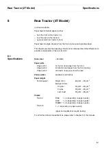
Page 169: ...rther data and specifications please refer to chapter 2 of this manual Noise level Paper paths Paper path 1 Paper path 2 Paper path 3 Park position Paper weight Fanfold paper Copies Tractor 1 Tractor...

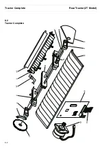
Page 170: ...Tractor Complete Rear Tractor 2T Model 8 2 8 2 Tractor Complete 4 1...

Page 171: ...Drive Wheel na na 62601 A 1 2 Guide B 1 3 Clamp B 1 10 Paper Guide 2 B 1 11 Motor Driver B 1 12 Motor Assy B 1 13 Cable Rear Tractor B 1 15 Paper Guide 3 Metal B 1 16 Paper End Sensor B 1 3rd Tractor...

Page 172: ...This page intentionally left blank...

Page 173: ...Cut height Cut time Specification of recommende forms Cutting accuracy Service life Weight Paper type Paper weight Copies Stacker 400 mm min form length 2 5 inches 6 35 cm 1000 ms 10 Only continous fo...

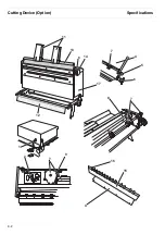
Page 174: ...Cutting Device Option Specifications 9 2 14 6 4 12 1 5 6 11 7 13 7 8 17 2 9 3 16 15 4...

Page 175: ...Cable B 1 2 Controller PCB Switch B 1 3 Motor incl Gears B 1 4 Housing Upper Part B 1 5 Drive Belt B 2 6 Toothed Wheel complete w Flat Spring and Axle B 1 7 Cutter Paper Transport Kit B 1 8 Blade Assy...

Page 176: ...This page intentionally left blank...

Page 177: ...2nd Front Tractor option 10 1 10 2nd Front Tractor option...

Page 178: ...emental Tractor Assy B 1 1 Tractor LE RI Complete 61064 61064 61064 A 1 3 Bearing 1 4 Toothed Wheel Z 50 M 0 7 1 Set 5 Side Panel Tractor 2 Right 1 Set 6 Side Panel Tractor 2 Left 1 7 Axle Tractor 2 S...

Page 179: ...Printer Stand Overview 11 1 11 Printer Stand 11 1 Overview...

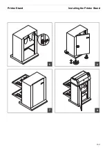
Page 180: ...Installing the Printer Stand Printer Stand 11 2 11 2 Installing the Printer Stand 1 2 3 4...

Page 181: ...Printer Stand Installing the Printer Stand 11 3 6 8 7 5...

Page 182: ...Installing the Printer Stand Printer Stand 11 4 9 10...

Page 183: ...rent form requires our explicit approval We reserve the right to make changes to this manual without notice All care has been taken to en sure accuracy of information contained in this manual However...

Page 184: ...Basingstoke Hampshire RG24 8PD England U K Phone 44 870 872 2888 Fax 44 870 872 2889 http www tallygenicom co uk CANADA TallyGenicom 125 Traders Boulevard 9 Missisauga Ontario L4Z 2E5 Canada Phone 1...

Reviews: