Testmodes and Troubleshooting
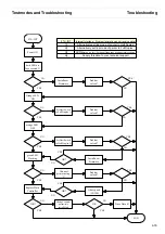
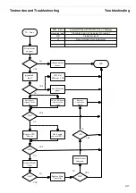
Display Message “Hardware Alarm”
4-25
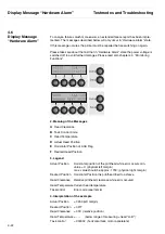
5. Analysis
The Desired Position and the Actual Position should be identical or close together.
By moving the printhead the function of the horizontal timing belt can be tested (value
of Actual Position is changing). The value of the head clearance is always a desired
position since there is no response of actual head clearance. Default standard = 18;
AGA = rel. position; max. value = 131 (i.e. after Initializing resp. power on).
Please analyse Task Control Code using the table below.
6. Task Control Codes
Task Control Code Meaning / Description
1
Horizontal Task – active
2
Horizontal Task – Motor is accelerating
4
Horizontal Task – Motor Break on
8
Vertical Movement – active
16
Color Motor – active
32
Motor Function Select – active
64
Motor Sheetfeeder – active
128
Adjustment Printhead Clearance – active
128 B
Adjustment AGA
– shift the horizontal drive belt one notch to the right and fasten belt
again according adjustments 6.1.1 – active
256
Paper Feed Sheetfeeder – active
512
Bell (sound) – active
1024
Shiftmagnet Printhead – active
2048
Papermovement – active
4096
Tear / View from ESC Seq. – active
8192
Paper Load – active
16384
Paper Eject – active 32768 Tear or View (general) – active
The
Task Control Codes
may occur as combinations.
Example:
code 1026
Meaning:
Shiftmagnet inside the printhead active while the horizontal motor is accel-
erated.
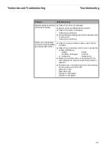
6.1 Hardware Alarm Task Code 1, 2, 3, 4 – horizontal task
Reason Solution
Printer stops intermittent in DRAFT
mode
Install newest firmware
Non Shielded interface cable according
IEEE 1284
Use a 2m max. shielded interface cable
IEEE 1284
Damaged or dirty timing strip
Clean*) or change strip
*) with a mild detergent
Head Adapter Cable
Mount new adapter cable
Defective logic
Install new main controller
Defective light barrier horizontal clock
– Clean intensive the contacts of the flat
cable from the light barrier – Change
light barrier
Noisy horizontal motor
Change CR motor
Summary of Contents for 2365
Page 1: ...Maintenance manual Matrix printer 2365 2380...
Page 2: ...This page intentionally left blank...
Page 8: ...This page intentionally left blank...
Page 10: ...This page intentionally left blank...
Page 20: ...This page intentionally left blank...
Page 32: ...Mechanical Functions Functional Description 3 12 right mark mark mark...
Page 35: ...Functional Description Electronic Functions 3 15 2365 2380 Electronic groups...
Page 128: ...This page intentionally left blank...
Page 134: ...Mechanical Adjustments Adjustments 6 6...
Page 136: ...Electrical Adjustments Adjustments 6 8...
Page 142: ...Housing Spare Parts and Schematics 7 2 7 1 Housing 7 1 1...
Page 144: ...Basic Printer Spare Parts and Schematics 7 4 7 2 1 Basic Printer 1 3 36...
Page 145: ...Spare Parts and Schematics Basic Printer 7 5 Basic Printer 2 3 462646...
Page 146: ...Basic Printer Spare Parts and Schematics 7 6 Basic Printer 3 3...
Page 151: ...This page intentionally left blank...
Page 164: ...Option Recognition Spare Parts and Schematics 7 24 7 10 Option Recognition...
Page 168: ...This page intentionally left blank...
Page 170: ...Tractor Complete Rear Tractor 2T Model 8 2 8 2 Tractor Complete 4 1...
Page 172: ...This page intentionally left blank...
Page 174: ...Cutting Device Option Specifications 9 2 14 6 4 12 1 5 6 11 7 13 7 8 17 2 9 3 16 15 4...
Page 176: ...This page intentionally left blank...
Page 177: ...2nd Front Tractor option 10 1 10 2nd Front Tractor option...
Page 179: ...Printer Stand Overview 11 1 11 Printer Stand 11 1 Overview...
Page 180: ...Installing the Printer Stand Printer Stand 11 2 11 2 Installing the Printer Stand 1 2 3 4...
Page 181: ...Printer Stand Installing the Printer Stand 11 3 6 8 7 5...
Page 182: ...Installing the Printer Stand Printer Stand 11 4 9 10...

