5-48
5
TROUBLESHOOTING
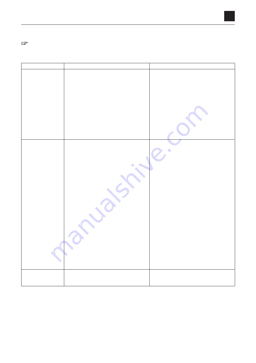
CONTROL VALVE
“4. Disassembly and assembly, Control valve”
The problems are listed individually in the table below, but in reality, many problems have multiple causes. Therefore, try to
check and eliminate each possible cause one at a time.
Symptoms
Major causes
Remedies
Oil leak from the spool
seal
• Flaw is on the sealing part or the seal lip is
worn out due to prolonged use
• Flaw (e.g., dents or scratches) on the sliding
part of the seal is caused by an external fac-
tor
• The lid that is pushing the sealing parts in
place is installed improperly (lid is distorted)
• Old paint remains on the seal sliding part of
the spool
• Tank pressure becomes too high for the per-
formance of the sealing material
• Replace with a new one.
• Repair or replace the spool.
• Correct the lid, and determine the partial
wear degree of the seal.
• Remove it by using thinner or mechanical
force.
When removing, take care not to damage the
spool surface or the seal lip.
• Remove the cause of the flow resistance.
Sliding part of the
spool is not smooth
• Foreign matter is caught in the sliding part of
the spool
• Oil film between the spool and the body be-
comes too thin due to the increased oil tem-
perature
• Lubrication is disabled due to deteriorated
oil
• Spool is worn out because of prolonged use
or of the unbalanced force applied
• Spool is bent by the external force
• Whole Valve is distorted due to the distortion
of the installation surface
• Valve is operated with the pressure or the
flow rate of out-of-spec
• Fixing bolts are over-tightened
• Oil stays in the lid (spring or detent) opposite
to the spool operation
• Overhaul and repair or replace.
• Try to decrease the oil temperature. If the re-
lief valve is started often, find the cause and
correct it.
• Oil should be replaced. The circuit also
should be overhauled in some cases.
• Replace the spool and the valve block as-
sembly.
• Check for the straightness of the spool, and
repair or replace.
• Check the distortion, independent of the
installation surface (loosening the bolts will
help).
• For pressure, measure it with a pressure
gauge. For flow rate, determine it by finding
out the movement speed and capacity of the
actuator.
• Check if the fixing bolts are tightened with the
specified torque. If not, tighten them again
with the specified torque.
• Oil may come out from the lid, if it is leaking
in the seal of the spool. If that is the case,
replace the seal.
When the actuator is
being raised, it drops
once
• Foreign matter is caught in the seat on the
load check valve, or the seat is damaged by
large foreign matter
• Disassemble the valve and overhaul or re-
place the faulty part(s).
CONTROL VALVE
Summary of Contents for TB 250
Page 1: ......
Page 3: ...1 1 SAFETY 1 Safety alert symbol 1 2 Safety precautions 1 3 Cautions when working 1 9...
Page 36: ...2 24 2 TIGHTENING TORQUE SERVICE DATA...
Page 38: ...2 26 2 HYDRAULIC CIRCUIT DIAGRAM SERVICE DATA Equipped with options 2 2...
Page 39: ...2 27 2 HYDRAULIC CIRCUIT DIAGRAM SERVICE DATA Equipped with angle blade and blade oat 1 2...
Page 40: ...2 28 2 HYDRAULIC CIRCUIT DIAGRAM SERVICE DATA Equipped with angle blade and blade oat 2 2...
Page 41: ...2 29 2 HYDRAULIC CIRCUIT DIAGRAM SERVICE DATA Equipped with high ow option 1 2...
Page 42: ...2 30 2 HYDRAULIC CIRCUIT DIAGRAM SERVICE DATA Equipped with high ow option 2 2...
Page 49: ......
Page 59: ...2 46 2 WIRE HARNESS WIRING DIAGRAM SERVICE DATA...
Page 60: ...2 47 2 WIRE HARNESS WIRING DIAGRAM SERVICE DATA...
Page 61: ...2 48 2 WIRE HARNESS WIRING DIAGRAM SERVICE DATA...
Page 62: ...2 49 2 WIRE HARNESS WIRING DIAGRAM SERVICE DATA...
Page 63: ...2 50 2 WIRE HARNESS WIRING DIAGRAM SERVICE DATA...
Page 64: ...2 51 2 WIRE HARNESS WIRING DIAGRAM SERVICE DATA...
Page 65: ...2 52 2 WIRE HARNESS WIRING DIAGRAM SERVICE DATA...
Page 66: ...2 53 2 WIRE HARNESS WIRING DIAGRAM SERVICE DATA...
Page 67: ...2 54 2 WIRE HARNESS WIRING DIAGRAM SERVICE DATA...
Page 68: ...2 55 2 WIRE HARNESS WIRING DIAGRAM SERVICE DATA...
Page 69: ...2 56 2 WIRE HARNESS WIRING DIAGRAM SERVICE DATA...
Page 70: ...2 57 2 WIRE HARNESS WIRING DIAGRAM SERVICE DATA...
Page 71: ...2 58 2 WIRE HARNESS WIRING DIAGRAM SERVICE DATA...
Page 72: ...2 59 2 WIRE HARNESS WIRING DIAGRAM SERVICE DATA...
Page 73: ...2 60 2 WIRE HARNESS WIRING DIAGRAM SERVICE DATA NAME STANDARD NO...
Page 74: ...2 61 2 WIRE HARNESS WIRING DIAGRAM SERVICE DATA...
Page 75: ...2 62 2 WIRE HARNESS WIRING DIAGRAM SERVICE DATA...
Page 76: ...2 63 2 WIRE HARNESS WIRING DIAGRAM SERVICE DATA...
Page 77: ...2 64 2 WIRE HARNESS WIRING DIAGRAM SERVICE DATA...
Page 78: ...2 65 2 WIRE HARNESS WIRING DIAGRAM SERVICE DATA...
Page 79: ...2 66 2 WIRE HARNESS WIRING DIAGRAM SERVICE DATA...
Page 80: ...2 67 2 WIRE HARNESS WIRING DIAGRAM SERVICE DATA...
Page 81: ...2 68 2 WIRE HARNESS WIRING DIAGRAM SERVICE DATA...
Page 92: ...3 11 3 CONTROL VALVE FUNCTION...
Page 108: ...4 3 4 SERVICE STANDARDS DISASSEMBLY AND ASSEMBLY Clearance for pin and bushing...
Page 352: ...ENGINE 6 Machine model Mounted engine TB250 4TNV88...


