


1-4
1
SAFETY PRECAUTIONS
SAFETY
Regularly replace the safety-critical parts
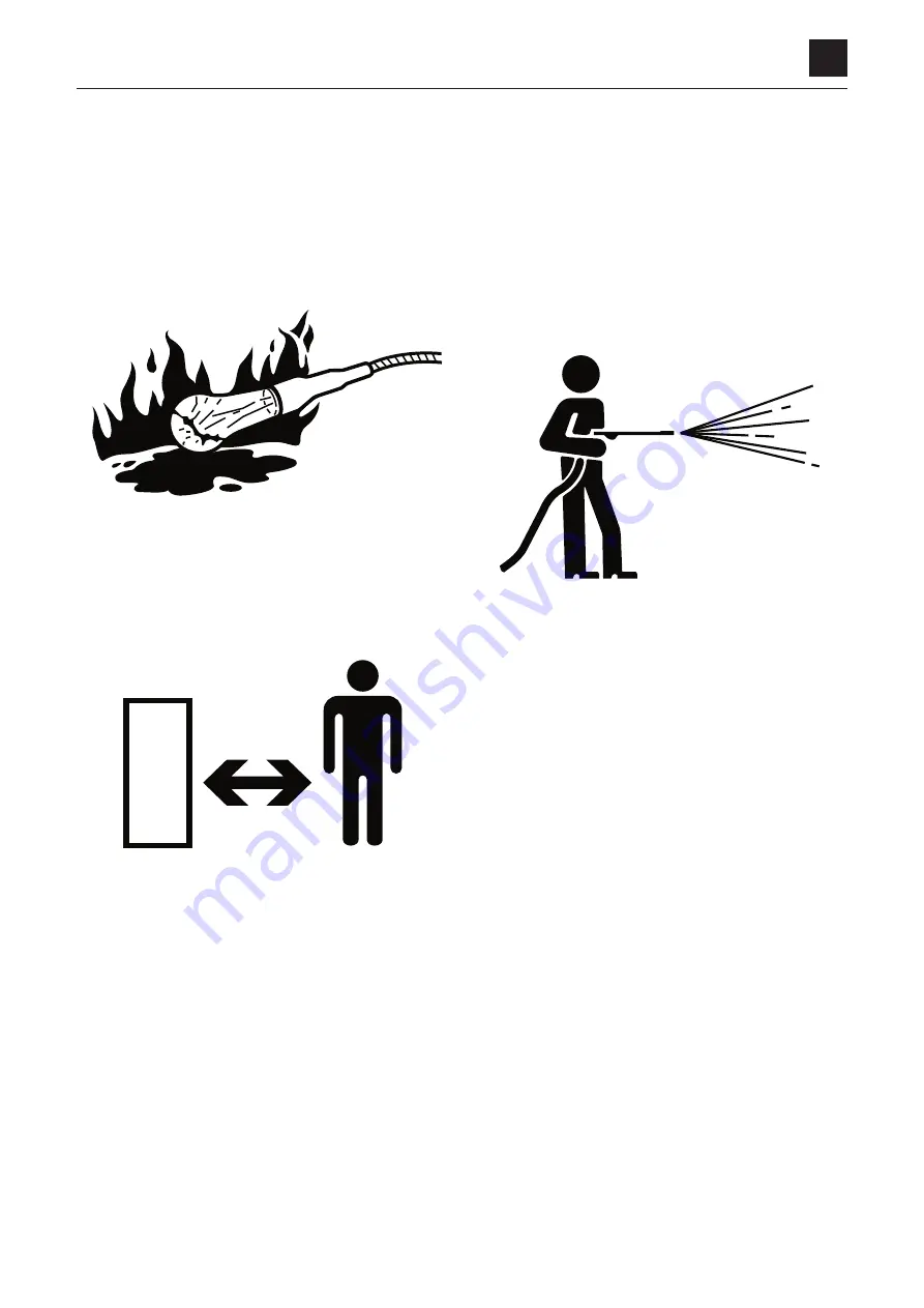
• Regularly replace fuel hoses to prevent a fire hazard.
Hoses wear out over time, even if they do not show any
symptom of wear.
• Regardless of the replacement schedule, replace imme-
diately if a symptom of wear is found.
Explosionproof lighting
To prevent an ignition or explosion, use explosion-proof
lights when inspecting fuel, oil, coolant or battery fluid.
Prohibit access by unauthorized persons
Do not allow unauthorized personnel in the work area while
working.
Take particular care that no unauthorized person is present
when grinding, welding or using a hammer.
Prepare the work area
• Select a level and firm ground on which to perform
maintenance work. Make sure that the work area is light
enough and well ventilated.
• Straighten any obstacle or dangerous object, remove
any spill of oil or grease and clean the work area.
When the canopy is tilted up
• If the canopy is raised or lowered while the engine is
moving, the machine may accidentally start moving, re-
sulting in severe injury to the maintenance personnel.
Make sure that the working equipment has been low-
ered to the ground and the engine has been turned off
before raising/lowering the canopy.
• When the canopy is tilted up, firmly secure the canopy
with a stopper to prevent it from falling.
Keep the machine clean
• Clean the machine before performing maintenance and
try to keep it clean.
• Before washing, cover the electrical parts with vinyl to
prevent water from entering, as this could cause a short-
circuit or malfunction. Do not use water or steam to
wash the battery, sensors, connectors or the operator’s
seat area.
Stop the engine before performing maintenance
Make sure the engine is stopped before starting inspection
or maintenance. If maintenance must be performed with
the engine running, always work as a 2-person team, com-
municating with each other.
• One of them must sit at the operator’s seat and stop the
engine whenever necessary. He/she must take care not
to touch the lever or pedal unless necessary.
• The one who performs maintenance must make sure to
keep his/her body or clothing away from the moving part
of the machine.
1BAA04Z
1BAA05Z
1BAA06Z
Summary of Contents for TB 250
Page 1: ......
Page 3: ...1 1 SAFETY 1 Safety alert symbol 1 2 Safety precautions 1 3 Cautions when working 1 9...
Page 36: ...2 24 2 TIGHTENING TORQUE SERVICE DATA...
Page 38: ...2 26 2 HYDRAULIC CIRCUIT DIAGRAM SERVICE DATA Equipped with options 2 2...
Page 39: ...2 27 2 HYDRAULIC CIRCUIT DIAGRAM SERVICE DATA Equipped with angle blade and blade oat 1 2...
Page 40: ...2 28 2 HYDRAULIC CIRCUIT DIAGRAM SERVICE DATA Equipped with angle blade and blade oat 2 2...
Page 41: ...2 29 2 HYDRAULIC CIRCUIT DIAGRAM SERVICE DATA Equipped with high ow option 1 2...
Page 42: ...2 30 2 HYDRAULIC CIRCUIT DIAGRAM SERVICE DATA Equipped with high ow option 2 2...
Page 49: ......
Page 59: ...2 46 2 WIRE HARNESS WIRING DIAGRAM SERVICE DATA...
Page 60: ...2 47 2 WIRE HARNESS WIRING DIAGRAM SERVICE DATA...
Page 61: ...2 48 2 WIRE HARNESS WIRING DIAGRAM SERVICE DATA...
Page 62: ...2 49 2 WIRE HARNESS WIRING DIAGRAM SERVICE DATA...
Page 63: ...2 50 2 WIRE HARNESS WIRING DIAGRAM SERVICE DATA...
Page 64: ...2 51 2 WIRE HARNESS WIRING DIAGRAM SERVICE DATA...
Page 65: ...2 52 2 WIRE HARNESS WIRING DIAGRAM SERVICE DATA...
Page 66: ...2 53 2 WIRE HARNESS WIRING DIAGRAM SERVICE DATA...
Page 67: ...2 54 2 WIRE HARNESS WIRING DIAGRAM SERVICE DATA...
Page 68: ...2 55 2 WIRE HARNESS WIRING DIAGRAM SERVICE DATA...
Page 69: ...2 56 2 WIRE HARNESS WIRING DIAGRAM SERVICE DATA...
Page 70: ...2 57 2 WIRE HARNESS WIRING DIAGRAM SERVICE DATA...
Page 71: ...2 58 2 WIRE HARNESS WIRING DIAGRAM SERVICE DATA...
Page 72: ...2 59 2 WIRE HARNESS WIRING DIAGRAM SERVICE DATA...
Page 73: ...2 60 2 WIRE HARNESS WIRING DIAGRAM SERVICE DATA NAME STANDARD NO...
Page 74: ...2 61 2 WIRE HARNESS WIRING DIAGRAM SERVICE DATA...
Page 75: ...2 62 2 WIRE HARNESS WIRING DIAGRAM SERVICE DATA...
Page 76: ...2 63 2 WIRE HARNESS WIRING DIAGRAM SERVICE DATA...
Page 77: ...2 64 2 WIRE HARNESS WIRING DIAGRAM SERVICE DATA...
Page 78: ...2 65 2 WIRE HARNESS WIRING DIAGRAM SERVICE DATA...
Page 79: ...2 66 2 WIRE HARNESS WIRING DIAGRAM SERVICE DATA...
Page 80: ...2 67 2 WIRE HARNESS WIRING DIAGRAM SERVICE DATA...
Page 81: ...2 68 2 WIRE HARNESS WIRING DIAGRAM SERVICE DATA...
Page 92: ...3 11 3 CONTROL VALVE FUNCTION...
Page 108: ...4 3 4 SERVICE STANDARDS DISASSEMBLY AND ASSEMBLY Clearance for pin and bushing...
Page 352: ...ENGINE 6 Machine model Mounted engine TB250 4TNV88...


