4-83
4
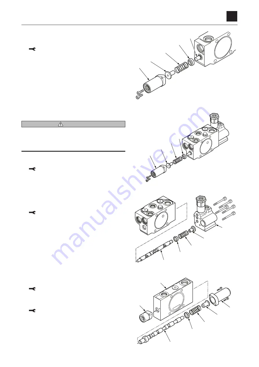
CONTROL VALVE
DISASSEMBLY AND ASSEMBLY
Pilot operated section
1. Remove the cap screws and cover (1), and then re-
move the O-ring from the cover (1).
Cap screw: 8.8 to 10.8 N·m
2. Remove the spring holder (2), spring (3) and spring
holder (4).
3. Remove the spool (5) from the housing.
• Make sure to insert the spool in the correct direc-
tion.
Boom section
WARNING
If the anti-drift valve is disassembled with the control
valve still installed, parts may be ejected due to the
internal pressure. Remove it after relieving the internal
pressure by gradually loosening the cap screw.
1. Remove the cap screws and cover (1), and then re-
move the O-ring from the cover.
Cap screw: 8.8 to 10.8 N·m
2. Remove the spring holder (2), spring (3) and spring
holder (4).
3. Take out the cap screws and housing (5), and then re-
move the O-ring from the housing.
• Do not further disassemble the anti-drift valve.
Cap screw: 8.8 to 10.8 N·m
4. Remove the spring holder (2), spring (3) and spring
holder (4).
5. Remove the spool assembly (6) from the housing.
• Make sure to insert the spool in the correct direc-
tion.
Switch valve
1. Remove the cap screws and cover (1), and then re-
move the O-ring from the cover (1).
Cap screw: 8.8 to 10.8 N·m
2. Remove the cap screws and cover (3), and then re-
move the O-ring from the cover (3).
Cap screw: 8.8 to 10.8 N·m
3. Remove the spring holder (4), spring (5) and spring
holder (6).
4. Remove the spool (7) from the housing.
• Be sure to insert the spool in the correct direction.
��������
�
�
�
�
�
��������
�
�
�
�
��������
�
�
�
�
�
��������
�
�
�
�
�
�
�
Summary of Contents for TB 250
Page 1: ......
Page 3: ...1 1 SAFETY 1 Safety alert symbol 1 2 Safety precautions 1 3 Cautions when working 1 9...
Page 36: ...2 24 2 TIGHTENING TORQUE SERVICE DATA...
Page 38: ...2 26 2 HYDRAULIC CIRCUIT DIAGRAM SERVICE DATA Equipped with options 2 2...
Page 39: ...2 27 2 HYDRAULIC CIRCUIT DIAGRAM SERVICE DATA Equipped with angle blade and blade oat 1 2...
Page 40: ...2 28 2 HYDRAULIC CIRCUIT DIAGRAM SERVICE DATA Equipped with angle blade and blade oat 2 2...
Page 41: ...2 29 2 HYDRAULIC CIRCUIT DIAGRAM SERVICE DATA Equipped with high ow option 1 2...
Page 42: ...2 30 2 HYDRAULIC CIRCUIT DIAGRAM SERVICE DATA Equipped with high ow option 2 2...
Page 49: ......
Page 59: ...2 46 2 WIRE HARNESS WIRING DIAGRAM SERVICE DATA...
Page 60: ...2 47 2 WIRE HARNESS WIRING DIAGRAM SERVICE DATA...
Page 61: ...2 48 2 WIRE HARNESS WIRING DIAGRAM SERVICE DATA...
Page 62: ...2 49 2 WIRE HARNESS WIRING DIAGRAM SERVICE DATA...
Page 63: ...2 50 2 WIRE HARNESS WIRING DIAGRAM SERVICE DATA...
Page 64: ...2 51 2 WIRE HARNESS WIRING DIAGRAM SERVICE DATA...
Page 65: ...2 52 2 WIRE HARNESS WIRING DIAGRAM SERVICE DATA...
Page 66: ...2 53 2 WIRE HARNESS WIRING DIAGRAM SERVICE DATA...
Page 67: ...2 54 2 WIRE HARNESS WIRING DIAGRAM SERVICE DATA...
Page 68: ...2 55 2 WIRE HARNESS WIRING DIAGRAM SERVICE DATA...
Page 69: ...2 56 2 WIRE HARNESS WIRING DIAGRAM SERVICE DATA...
Page 70: ...2 57 2 WIRE HARNESS WIRING DIAGRAM SERVICE DATA...
Page 71: ...2 58 2 WIRE HARNESS WIRING DIAGRAM SERVICE DATA...
Page 72: ...2 59 2 WIRE HARNESS WIRING DIAGRAM SERVICE DATA...
Page 73: ...2 60 2 WIRE HARNESS WIRING DIAGRAM SERVICE DATA NAME STANDARD NO...
Page 74: ...2 61 2 WIRE HARNESS WIRING DIAGRAM SERVICE DATA...
Page 75: ...2 62 2 WIRE HARNESS WIRING DIAGRAM SERVICE DATA...
Page 76: ...2 63 2 WIRE HARNESS WIRING DIAGRAM SERVICE DATA...
Page 77: ...2 64 2 WIRE HARNESS WIRING DIAGRAM SERVICE DATA...
Page 78: ...2 65 2 WIRE HARNESS WIRING DIAGRAM SERVICE DATA...
Page 79: ...2 66 2 WIRE HARNESS WIRING DIAGRAM SERVICE DATA...
Page 80: ...2 67 2 WIRE HARNESS WIRING DIAGRAM SERVICE DATA...
Page 81: ...2 68 2 WIRE HARNESS WIRING DIAGRAM SERVICE DATA...
Page 92: ...3 11 3 CONTROL VALVE FUNCTION...
Page 108: ...4 3 4 SERVICE STANDARDS DISASSEMBLY AND ASSEMBLY Clearance for pin and bushing...
Page 352: ...ENGINE 6 Machine model Mounted engine TB250 4TNV88...