4-157
4
TRAVEL MOTOR
DISASSEMBLY AND ASSEMBLY
Inspection and adjustment
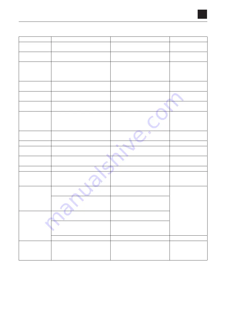
Use limit for parts
Part
Area checked
Judgment criteria
Treatment
Floating seal
Sliding surface
Abnormal scratches, wear or scorch-
ing on the surface
Replace
Angular bearing
Rolling surface
Abnormal scratches, wear or flaking
on the ball or race.
Replace
Planetary gear
Gear tooth surface
Abnormal scratches, wear or flaking
of the tooth surface (if pitting covers
10% or more of the area engaging
with the tooth surface).
Replace
Inner race
Rolling surface
Abnormal scratches, wear or flaking
on the rolling surface
Replace
Needle
Needle surface
Abnormal scratches, wear or flaking
on the surface
Replace
Thrust washer
Sliding surface
Abnormal scratches, wear or scorch-
ing on the surface
Replace
Housing, sun gear,
drive gear
Gear tooth surface
Abnormal scratches, wear or flaking
of the tooth surfaces (if pitting cov-
ers 10% or more of the area engag-
ing with the tooth surface).
Replace
Thrust plate
Sliding surfaces
Abnormal scratches, wear or scorch-
ing on the surface
Replace
O-ring
––
––
Replace
Shaft
Oil seal surface
Abnormal scratches, wear or scorch-
ing on the surface
Replace
Ball bearing
Sliding surfaces
Abnormal scratches or flaking on the
ball or race.
Replace
Oil seal
––
––
Replace
Swash plate
Sliding surface with the piston as-
sembly
Abnormal scratches (0.02 mm or
more), wear or scorching on the sur-
faces
Replace
Cylinder block
Cylinder block-to-piston assembly
clearance
0.04 mm or more
Repair by lapping
(#1000) or replace
both cylinder block
and piston assembly.
Sliding surface with the valve plate
Abnormal scratches (0.02 mm or
more), wear or scorching on the sur-
faces
Piston assembly
Piston assembly-to-cylinder block
clearance
0.04 mm or more
Sliding surface with the swash plate Abnormal scratches (0.02 mm or
more), wear or scorching on the sur-
faces
Play of piston shoe
0.04 mm or more
Replace
Valve plate
Sliding surface with the cylinder
block
Abnormal scratches (0.02 mm or
more), wear or scorching on the sur-
faces
Repair by lapping
(#1000) or replace
both cylinder block
and piston assembly.
Summary of Contents for TB 250
Page 1: ......
Page 3: ...1 1 SAFETY 1 Safety alert symbol 1 2 Safety precautions 1 3 Cautions when working 1 9...
Page 36: ...2 24 2 TIGHTENING TORQUE SERVICE DATA...
Page 38: ...2 26 2 HYDRAULIC CIRCUIT DIAGRAM SERVICE DATA Equipped with options 2 2...
Page 39: ...2 27 2 HYDRAULIC CIRCUIT DIAGRAM SERVICE DATA Equipped with angle blade and blade oat 1 2...
Page 40: ...2 28 2 HYDRAULIC CIRCUIT DIAGRAM SERVICE DATA Equipped with angle blade and blade oat 2 2...
Page 41: ...2 29 2 HYDRAULIC CIRCUIT DIAGRAM SERVICE DATA Equipped with high ow option 1 2...
Page 42: ...2 30 2 HYDRAULIC CIRCUIT DIAGRAM SERVICE DATA Equipped with high ow option 2 2...
Page 49: ......
Page 59: ...2 46 2 WIRE HARNESS WIRING DIAGRAM SERVICE DATA...
Page 60: ...2 47 2 WIRE HARNESS WIRING DIAGRAM SERVICE DATA...
Page 61: ...2 48 2 WIRE HARNESS WIRING DIAGRAM SERVICE DATA...
Page 62: ...2 49 2 WIRE HARNESS WIRING DIAGRAM SERVICE DATA...
Page 63: ...2 50 2 WIRE HARNESS WIRING DIAGRAM SERVICE DATA...
Page 64: ...2 51 2 WIRE HARNESS WIRING DIAGRAM SERVICE DATA...
Page 65: ...2 52 2 WIRE HARNESS WIRING DIAGRAM SERVICE DATA...
Page 66: ...2 53 2 WIRE HARNESS WIRING DIAGRAM SERVICE DATA...
Page 67: ...2 54 2 WIRE HARNESS WIRING DIAGRAM SERVICE DATA...
Page 68: ...2 55 2 WIRE HARNESS WIRING DIAGRAM SERVICE DATA...
Page 69: ...2 56 2 WIRE HARNESS WIRING DIAGRAM SERVICE DATA...
Page 70: ...2 57 2 WIRE HARNESS WIRING DIAGRAM SERVICE DATA...
Page 71: ...2 58 2 WIRE HARNESS WIRING DIAGRAM SERVICE DATA...
Page 72: ...2 59 2 WIRE HARNESS WIRING DIAGRAM SERVICE DATA...
Page 73: ...2 60 2 WIRE HARNESS WIRING DIAGRAM SERVICE DATA NAME STANDARD NO...
Page 74: ...2 61 2 WIRE HARNESS WIRING DIAGRAM SERVICE DATA...
Page 75: ...2 62 2 WIRE HARNESS WIRING DIAGRAM SERVICE DATA...
Page 76: ...2 63 2 WIRE HARNESS WIRING DIAGRAM SERVICE DATA...
Page 77: ...2 64 2 WIRE HARNESS WIRING DIAGRAM SERVICE DATA...
Page 78: ...2 65 2 WIRE HARNESS WIRING DIAGRAM SERVICE DATA...
Page 79: ...2 66 2 WIRE HARNESS WIRING DIAGRAM SERVICE DATA...
Page 80: ...2 67 2 WIRE HARNESS WIRING DIAGRAM SERVICE DATA...
Page 81: ...2 68 2 WIRE HARNESS WIRING DIAGRAM SERVICE DATA...
Page 92: ...3 11 3 CONTROL VALVE FUNCTION...
Page 108: ...4 3 4 SERVICE STANDARDS DISASSEMBLY AND ASSEMBLY Clearance for pin and bushing...
Page 352: ...ENGINE 6 Machine model Mounted engine TB250 4TNV88...


