4-142
4
CYLINDERS
DISASSEMBLY AND ASSEMBLY
Inspection and adjustment
Inspection after disassembly
Clean each part thoroughly with cleaning oil, then carry out
the following checks. When a cylinder has been disassem-
bled, replace all the seals with new ones.
1. Piston rod
• Replace the rod if there are cracks.
• If the threads are damaged, repair them or replace
the rod.
• If the plating layer of the plated portion is broken,
rusted or scratched, replace the rod.
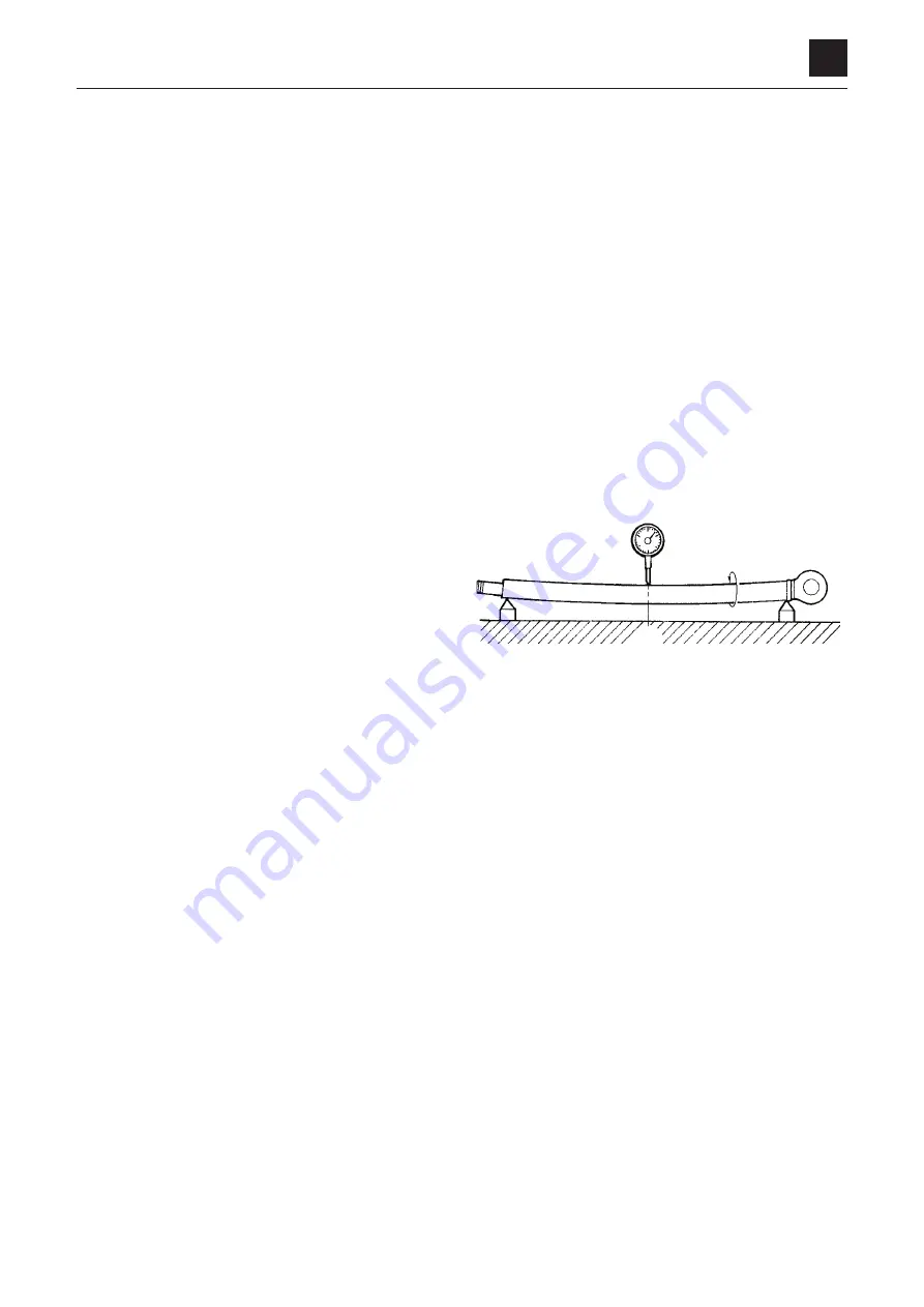
• If the rod is bent more than the limit of 1 mm in 1 m,
replace it. (For the measurement method, refer to
the figure on the right.)
• If the inner diameter of the clevis bushing is worn,
replace the bushing.
Measuring the bend
a. Support the portion of the rod with the same diam-
eter at both ends on V-blocks.
b. Set a dial gauge at the center between the two
blocks.
c. Rotate the rod and take a reading of the maximum
and minimum run-out indicated by the dial gauge. If
the bending of the rod is within the above limit, yet is
bent a lot in a small distance so that it will not move
smoothly, replace the rod if it makes a squeaking
sound in the operation test after reassembly or if it
catches during movement.
2. Tube
• If there are cracks in the welded portion, replace the
tube.
• Replace the tube if the inside surface is scratched or
if it leaks hydraulic oil.
• If the inner diameter of the clevis bushing is worn,
replace the bushing.
3. Rod cover
• If the bushing inner diameter is worn and the clear-
ance with the piston rod is greater than 0.25 mm,
replace the bushing.
• If the inside surface of the bushing is scratched, and
the scratches are deeper than the depth of the coat-
ing layer, replace the bushing.
4LAA37Z
1/2
Summary of Contents for TB 250
Page 1: ......
Page 3: ...1 1 SAFETY 1 Safety alert symbol 1 2 Safety precautions 1 3 Cautions when working 1 9...
Page 36: ...2 24 2 TIGHTENING TORQUE SERVICE DATA...
Page 38: ...2 26 2 HYDRAULIC CIRCUIT DIAGRAM SERVICE DATA Equipped with options 2 2...
Page 39: ...2 27 2 HYDRAULIC CIRCUIT DIAGRAM SERVICE DATA Equipped with angle blade and blade oat 1 2...
Page 40: ...2 28 2 HYDRAULIC CIRCUIT DIAGRAM SERVICE DATA Equipped with angle blade and blade oat 2 2...
Page 41: ...2 29 2 HYDRAULIC CIRCUIT DIAGRAM SERVICE DATA Equipped with high ow option 1 2...
Page 42: ...2 30 2 HYDRAULIC CIRCUIT DIAGRAM SERVICE DATA Equipped with high ow option 2 2...
Page 49: ......
Page 59: ...2 46 2 WIRE HARNESS WIRING DIAGRAM SERVICE DATA...
Page 60: ...2 47 2 WIRE HARNESS WIRING DIAGRAM SERVICE DATA...
Page 61: ...2 48 2 WIRE HARNESS WIRING DIAGRAM SERVICE DATA...
Page 62: ...2 49 2 WIRE HARNESS WIRING DIAGRAM SERVICE DATA...
Page 63: ...2 50 2 WIRE HARNESS WIRING DIAGRAM SERVICE DATA...
Page 64: ...2 51 2 WIRE HARNESS WIRING DIAGRAM SERVICE DATA...
Page 65: ...2 52 2 WIRE HARNESS WIRING DIAGRAM SERVICE DATA...
Page 66: ...2 53 2 WIRE HARNESS WIRING DIAGRAM SERVICE DATA...
Page 67: ...2 54 2 WIRE HARNESS WIRING DIAGRAM SERVICE DATA...
Page 68: ...2 55 2 WIRE HARNESS WIRING DIAGRAM SERVICE DATA...
Page 69: ...2 56 2 WIRE HARNESS WIRING DIAGRAM SERVICE DATA...
Page 70: ...2 57 2 WIRE HARNESS WIRING DIAGRAM SERVICE DATA...
Page 71: ...2 58 2 WIRE HARNESS WIRING DIAGRAM SERVICE DATA...
Page 72: ...2 59 2 WIRE HARNESS WIRING DIAGRAM SERVICE DATA...
Page 73: ...2 60 2 WIRE HARNESS WIRING DIAGRAM SERVICE DATA NAME STANDARD NO...
Page 74: ...2 61 2 WIRE HARNESS WIRING DIAGRAM SERVICE DATA...
Page 75: ...2 62 2 WIRE HARNESS WIRING DIAGRAM SERVICE DATA...
Page 76: ...2 63 2 WIRE HARNESS WIRING DIAGRAM SERVICE DATA...
Page 77: ...2 64 2 WIRE HARNESS WIRING DIAGRAM SERVICE DATA...
Page 78: ...2 65 2 WIRE HARNESS WIRING DIAGRAM SERVICE DATA...
Page 79: ...2 66 2 WIRE HARNESS WIRING DIAGRAM SERVICE DATA...
Page 80: ...2 67 2 WIRE HARNESS WIRING DIAGRAM SERVICE DATA...
Page 81: ...2 68 2 WIRE HARNESS WIRING DIAGRAM SERVICE DATA...
Page 92: ...3 11 3 CONTROL VALVE FUNCTION...
Page 108: ...4 3 4 SERVICE STANDARDS DISASSEMBLY AND ASSEMBLY Clearance for pin and bushing...
Page 352: ...ENGINE 6 Machine model Mounted engine TB250 4TNV88...