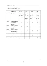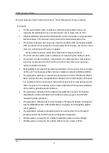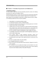
background image


TP950 Instrument Manual


Rev. J   

14 

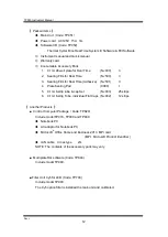
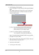
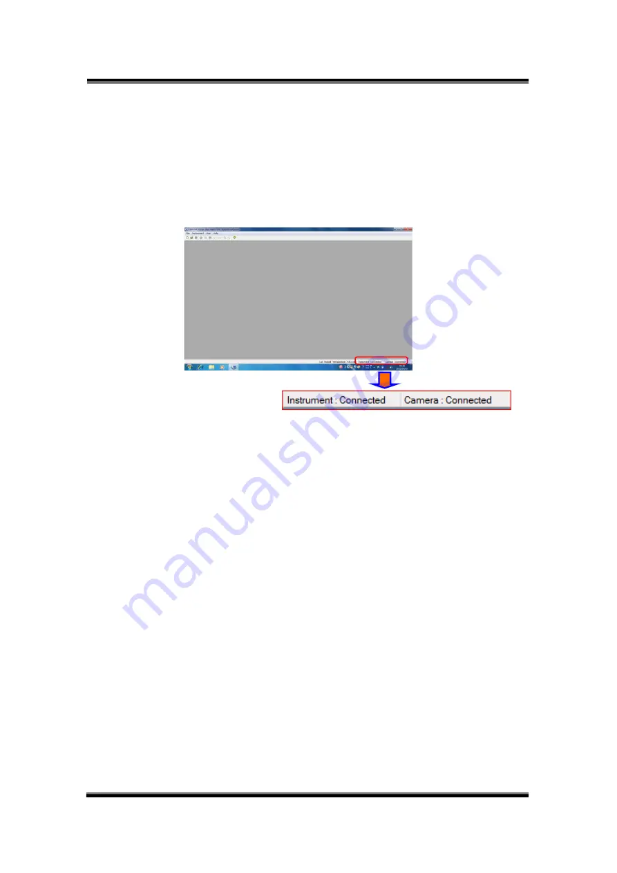
6.  Turn on the power of a control computer. 

An icon on the desktop of a control computer is double-clicked and software is 

started.


When message of "Instrument: Connected" and "Camera: Connected" went 

out to the lower right of a screen, a connection of the body and a control 

computer normally connected. 


【 

Caution

  】 

When the message of [Instrument: Disconnected] and /or 

                        [Camera: Disconnected] appear in the screen lower right,   

                        terminate software at once and restart the software. 


【 

Caution

  】 

Connect an AC adapter to a computer power supply. 

                          There is a fear that a computer stops only by battery use. 


Refer to 

“The operation manual of PC-Software V6.00” for a way of reactions 

and analysis of real time PC software. 


7.  After  a  connection  with  LAN  mode  is  disconnected  in  Remote  >  Disconnect 

when ending. Software is closed in File > Exit. 


8.  Shut down the control computer. 


9.  Turn off the power of the main body. 


Summary of Contents for Thermal Cycler Dice Real Time System III

Page 1: ... TP980 TP990 LCD application software V 1 00 Real Time System Software V 6 00 OS Windows 7 8 1 Instrument Manual TAKARA BIO INC Attention Thermal Cycler Dice TM Real Time System Instrument Manual should be stored for reference in a secure and accessible location ...

Page 2: ...Time PCR Quantification Method The purchase of this product includes a limited non transferable license for all fields other than human or veterinary in vitro diagnostics under specific claims of U S Patent Nos 6 174 670 6 569 627 6 303 305 and 6 503 720 owned by the University of Utah Research Foundation and licensed to Idaho Technology Inc and Roche Diagnostics GmbH Thermal Cycler Dice is a trad...

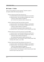
Page 3: ...m 15 Chapter 3 Part Names and Functions 16 Chapter 4 Explanation of Screens 21 1 System Startup and Shut Down 21 2 Home Screen 23 Chapter 5 Maintenance 24 1 Self diagnostic Function 24 2 Daily Inspection 27 Sample Block Cleaning 28 Chapter 6 Other Settings 31 1 Enter Other setting 31 2 Explanation of each function 32 Chapter 7 Troubleshooting 35 Computer settings 39 Chapter 8 Specifications 40 Cha...

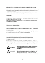
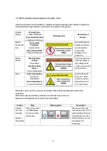
Page 4: ...ities Refer to the Warrantycard included with this product for detailed description of the Warranty conditions and period This product is designed to ultimate safety standards Nevertheless should any safety related issues arise users are requested to immediately contact the nearest sales agent Precautions safety and accident prevention for System Use 1 Danger Warnings The various messages and labe...

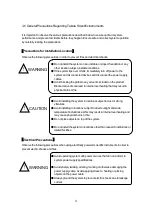
Page 5: ...ternal overheating that may result in physical burns or fire Avoid installing the system in locations subject to dust or strong vibrations Avoid installing in locations subject to direct sunlight and wide temperature fluctuations as this may result in internal overheating and may cause physical burns or fire Do not place objects on top of the system Do not install the system in locations other tha...

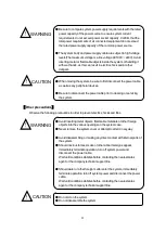
Page 6: ...he system Other precautions Observe the following precautions in order to prevent electric shocks and fires Avoid inserting metal objects flammable materials or other foreign objects into the various openings on the system case Never remove the system cover or attempt to alter it in anyway Avoid disassembling or making any direct contact with internal parts of the system Should noxious fumes smoke...

Page 7: ...sion Cordon d alimentation The case and power cable are subject to high voltage levels so take care to avoid electric shocks Burns High Temperatures Heat cover Heat block Haute Température Couvercle Chauffant Avoid touching the heat cover which reaches very high temperatures and may cause burns Please be sure to use 0 1mL type for the reaction tube and the reaction plate used by this equipment Whe...

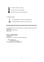
Page 8: ...tion of the main power switch Precautions against Transferring or Copying Content of This Document The content of this document cannot be transferred or copied without the express permission of the copyright holder Copyright holder TAKARA BIO INC Printed in Japan Contact TAKARA BIO INC TAKARA BIO INC NOJI HIGASHI 7 4 38 KUSATSU SHIGA 525 0058 JAPAN http www takara bio com Technical Inquiries Conta...

Page 9: ...nment Inspection Software Japanese only 3 Thermal Cycler Dice Real Time System Control Computer Code TP820 TP980 Thermal Cycler Dice Real Time System III with PC MRQ 1 Thermal Cycler Dice Real Time System III Main Unit Code TP951 2 Thermal Cycler Dice Real Time System III Software Code TP952 1 Real Time System Software for Research 2 Food Environment Inspection Software Japanese only 3 Thermal Cyc...

Page 10: ...er Dice Real Time System III with PC Thermal Cycler Dice Real Time System III with PC MRQ Thermal Cycler Dice Real Time System III Cy5 with PC TP951 Thermal Cycler Dice Real Time System III Main body TP952 Thermal Cycler Dice Real Time System III Software TP820 Thermal Cycler Dice Real Time System III Control Computer TP840 Multi plate RQ TP703 Filter Unit Cy5 for LED ...

Page 11: ...ctions Expandability is provided for by allowing installation of a maximum of four 4 types of filter unit Two fluorescent filter units are installed as standard FAM and ROX The application software is user friendly and similar to TP700 TP800 and TP900 Basic settings are easy and application settings provide a high degree of freedom It is possible to set the fluorescent measurement point and to vie...

Page 12: ...rom electrical equipment that generates strong magnetic fields electrical fields and high frequencies Avoid locations near equipment that generate noise caused by electrical motors and transformers 6 Choose a flat location capable of withstanding the design weight of the system 7 The installation environment must be within 15 to 30ºC temperature range and a 20 to 80 relative humidity range 8 Avoid...

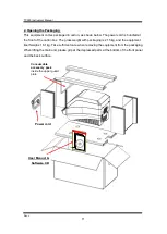
Page 13: ...on box The gross weight with packaging is 21 5 kg and the equipment itself weighs 16 1 kg Take sufficient care when removing the equipment from the packaging When lifting the main unit please grip at the depressed parts at the bottom of the front panel and the back surface Consumable accessory pack inside the upper guard plate Power cord User Manual Software CD ...

Page 14: ...Plate Sealing Pad 9090 1 5 0 1ml 8 strip tube cap Set NJ903 25 strips 6 0 1ml 8 strip Tube individual Flat Caps NJ902 12 strips Another Products Control Computer Package Code TP820 Include model TP970 TP980 and TP990 Notebook PC AC adaptor for Notebook PC Microsoft Office Home and Business 2013 MPI card MPI Microsoft Product Identifier LAN cable Cross type 2m NOTE The contents of the accessory pac...

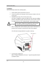
Page 15: ...ed the power cord ensure with a 100 to 125 VAC If power line voltage will be over 125 V change the power cord for suitable voltage 4 When connecting with a control computer please connect a LAN cable of an accessory the cross type to a terminal for the back of the equipment A LAN cable Cross type attaches to a system accessory 5 Turn the system equipment on Refer to Chapter 4 Explanation of Screen...

Page 16: ... of Instrument Disconnected and or Camera Disconnected appear in the screen lower right terminate software at once and restart the software Caution Connect an AC adapter to a computer power supply There is a fear that a computer stops only by battery use Refer to The operation manual of PC Software V6 00 for a way of reactions and analysis of real time PC software 7 After a connection with LAN mod...

Page 17: ...arrying the system be sure to place both hands on each side of the system and lift and carry in a balanced way 4 Make sure that the new location conforms to the installation requirements described in section 1 Installation Conditions in Chapter 2 5 Follow the installation procedures outlined in section 3 Installation in Chapter 2 Moving to a New Site When moving the system to a new site clean it c...

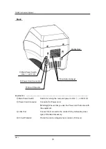
Page 18: ...TP950 Instrument Manual Rev J 16 Chapter 3 Part Names and Functions Exterior Lid Closed Lid Handle LCD Display Power Button Ventilation intake USB Port Power Lamp ...

Page 19: ...ration by heating the top of the Reaction plate The Lid aiso allows through path of excitation light and emission light Caution Do not insert fingers The Lid plate becomes very hot 108 110 Sample Block Place the Reaction plate or Tube on the Reaction block Caution Be careful to avoid injuries from burns The block heats up to a maximum of 100 LCD Display USB Port Lid Handle Lid Ventilation intake L...

Page 20: ...entilation intake Openings in the main unit for providing internal cooling by air ventilation Caution Do not cover the Ventilation intakes Lid Lock Catch Catch for the Lid Lock cylinder Power Lamp Show a power supply state of the main unit light off Main power switch is off turns on in orange Main power switch is turned on but not start Operation Software yet shines in green Program is running now...

Page 21: ...tor for Power cord Warning Ensure that you use the Power cord that came with the equipment LAN Port Connect the main unit to the control PC by LAN cable cross type of standard accessory Circuit Protector Protect the main unit against over current 10A over Power Cord Connector Main Power Switch ON OFF Ventilation Exhaust LAN Port Circuit Protector ...

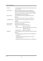
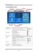
Page 22: ...ation Selector To change communication mode touch the selector and then touch Yes button on the message screen Default mode is selected on Mode Select Instrument Other Setting Ethernet Setup Local Mode The main unit is controlled by the LCD touch panel Remote Mode The main unit is controlled by the LAN connection PC Lid status Closed the Lid Closed Opened the Lid Open Lid Temperature Show the curr...

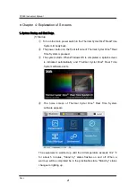
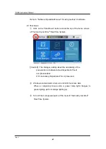
Page 23: ... Time System is pressed The system starts When Windows OS is completed a splash screen is indicated automatically and Thermal Cycler Dice Real Time System software starts The home screen of Thermal Cycler Dice Real Time System software appears The equipment is warmed up until the lid temperature exceeds 102 for about 5 minutes Stand by status flashes on and off When a warm up will be completed be ...

Page 24: ...em Caution The dialogue asking about the advisability of the preservation is indicated about Experiment File of non preservation If it s necessary Experiment File is preserved Windows end and wait a moment until LCD becomes dark When a complete process ends a power lamp light changes to green lighting up from orange lighting up Turn off the main power switch of the bock of Thermal Cycler Dice Real...

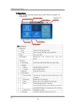
Page 25: ...cal Calibration procedure Thermal Service mode function Diagnosis Diagnostic test function Other Setting Ethernet Setup Set ether net connection and select default mode Local or Remote Brightness Brightness of LCD backlight Beep Beep sound of LCD ON OFF and sound level Mode Select language English or Japanese Save experiment file type rtp for research or rta for EFI Set default PCR heat cool rate ...

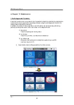
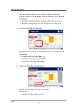
Page 26: ...function for Sample Block temperature efficiency In addition the status of the temperature control function can be tracked by performing periodic self diagnostic tests There are 3 items in the diagnostic test Rate Test Tests the heating and cooling rates Cycle Test Tests the cycle time overshoot and undershoot Up Down Test Measures the heating and cooling time required to go up 98 and then down to...

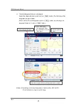
Page 27: ...nue the next diagnostic touch on Stop button once Making sure appeared Stand by touch on Start button Note Operating environment temperature must be within 20 to 23 If not Performance may be out of range 1 Check diagnostic items 2 Click Start button If not appeared Stand by click Stop once and Start again 3 It is progressive time Results are displayed when self diagnostics are complete ...

Page 28: ...r second Maximum cooling rate greater than or equal to 3 0 C per second Cycle Test Program Execution Screen Program Contents 94 C 30 seconds 55 C 30 seconds 72 C 30 seconds Specification Overshoot less than or equal to 0 5 C Undershoot less than or equal to 0 5 C Length of run time Within 4 minutes Up Down Test Program Execution Screen Program Contents 98 C 1 minute 4 C 1 minute Specification Leng...

Page 29: ...lifetime Clean the Lid and the main unit Wipe the outside of the equipment with a cloth soaked a little in a neutral detergent Then wipe with a dry cloth Verify the sliding action of the Lid Wipe off any dirt or debris around the rails Wiping the Lid rails with a dry cloth is sufficient It is not necessary to lubricate Disinfect by wiping with a 10 bleach solution Allow to leave for 10 minutes the...

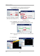
Page 30: ...heck whether the Sample Block is soiled dirty tighten the Lid without putting anything on theSample Block and then photograph in FAM and ROX modes and verify that fluorescence is not visible If dirty clean using ethanol and or tap water by swabs Prepare the followings Cotton swab slender type Ethanol 100 Procedure Verify that there is no plate on the Sample Block and close the Lid Open Instrument ...

Page 31: ...Calibration screen A confirmation message is displayed when photographing is complete Click OK Note When Lid temperature up to 103 and more operating program start to run Verify the image Set Expo 400 And Gain 4 Set FAM dye TakePicture button Touch the area of Expo 200 then appear the keyboard Input 400 and touch OK button Similar to step change Gain 1 to 4 Touch Zoom for expansion ...

Page 32: ... dirt wipe off it by a swab with ethanol or tap water in the same way Lastly wipe by a dry swab in all wells Note When solution of ethanol or water leaves in well correct fluorescent signal can not be detected Caution Be sure to verify the image with both FAM and ROX Sometimes soiling is not visible with FAM but is visible with ROX and vice versa When Option filters HEX VIX Cy5 are attached Be sur...

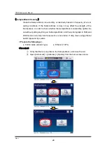
Page 33: ...ter 6 Other Settings In other setting Other Setting 1 Ethernet Setup 2 Brightness 3 Beep 4 Mode 5 Date Time The respective functions are explained in the next 1 Enter Other setting Select Instrument from Home screen and click Other Setting ...

Page 34: ...setting 255 255 255 0 Operation Local The unit is controlled by itself Selected Local mode can t be connected to the unit from the outside control PC Remote The unit is controlled by the outside control PC 2 Brightness The function as which the brightness of the liquid crystal display is set The brightness of the LCD is adjusted by key or the slide bar Click OK button Default setting is level 10 ...

Page 35: ...terface on the LCD screen English Default setting Fonts in the LCD screen are in English 日本語 Fonts are In Japanese File Type Select the experiment file type of Research or FEI Research Default setting Save the experiment file type rtp for the research software This file type can be opened by the research software only FEI Save the experiment file type rta for the FEI Food Environment Inspect softw...

Page 36: ...ate and cool rate are controlled temperature in PCR cycle 5 Date Time Set the date Year Month Day and time Hour minute second When Box of each set value is clicked numerical keyboard for value input is indicated So it s changed to the value and click OK button The set value is reflected An error for about one 1 minute may form a month Suggest that adjusting the time periodically ...

Page 37: ...r An allophone is heard when turn on the power The retainer which makes the movement of filter movement smooth is cross with a stopper When a retainer is cross with a stopper an allophone is corrected and doesn t continue Use just as it is A filter changer doesn t stop by abnormality of a position sensor A motor keeps moving and an allophone doesn t stop Turn the unit off immediately A replacement...

Page 38: ...e stepping motor has malfunctioned The part needs to be replaced and adjusted Make a request for repair The position detecting sensor has malfunctioned The temperature of the heat sink became hot and the safe function operated A Cooling fan is not going around Confirm the use environment of the product the room temperature Confirm whether a vent isn t blocked up When a fan for cooling is in troubl...

Page 39: ...ightness of an LED light source is low A LED power supply or a LED has a problem Make a request for repair it An optical component is soiled Resolution of an optical component check and cleaning are needed Well of the sample block is dirty Clean wells of the sample block Refer to chapter 5 2 Dalily Inspection Sample Block Cleaning Symptom Cause Correspondence Self diagnostic Function The rate of t...

Page 40: ...up version isn t installed Install the dot Net Framework 4 0 The PCR program does not start The file which is being operated is measured data in the past Run a created file When using setting of the measurement performed in the past run file read as a template When starting the program the message Please put the lid on is displayed The Lid is no closed completely Close the Lid completely The progr...

Page 41: ...lect Personalize and clic iii Clic Screen Saver iv Select None on Screen Saver and then clic Change power settings v Select High performance and then clic Change plan settings vi Select Never in all selectors and clic Save changes then Change advanced power settings vii Confirm the following settings ...

Page 42: ...ard increments of 0 1 Main Unit Display Power Lamp 2 color LED Orange Green Rate of Temperature Increase Decrease Maximumheatingrate 4 5 second andmore Fastmode Maximumcoolingrate 4 0 second andmore Fastmode Run Modes Fast mode Normal mode similar to TP800 Dissociation Analysis 20 95 increments of 0 5 Default set 60 95 Lid Holding Temperature When set program temperature to 20 or more Lid temperat...

Page 43: ...imensions Weight 376 W x 259 D x 28 H mm 2 2kg Main Unit only Specification OS Windows 8 1 Professional 64bit English Buck up DVD Windows 8 1 DVD resource English CPU Intel Core i 5 4310U プロセッサ 2 0GHz Memory 4GB Hard Disk 500GB LCD Size 15 6 inch HD 1366x768 16 9 with Touch screen Optical Drive stationary type DVD super multi drive USB 2 0 port x 2 USB3 0 port x 2 Standard accessory AC adaptor for...

Page 44: ...strip tubes Individually attached caps Each one of use is also possible 0 1mL 8 strip tubes and 8 strip caps Code Product Quantity Comments NJ903 0 1ml 8 strip tube cap Set 120 pair strips Set of 8 strip tubes and 8 strip caps When using any tubes please make and use an empty tube in the four corners on the sample block for buckling prevention Option Filter Units TP700 TP950 Code Product Quantity ...

Page 45: ...r Dice Real Time System Software is being installed for the first time perform the steps described in section 1 Install If the software version is being upgraded first perform the steps in section 2 Uninstall and then start the procedure from section 1 CONTENTS Windows 7 English A Install Uninstall Add 1 2 Windows 8 1 English B Install Uninstall Add 1 6 ...

Page 46: ...e setup exe file inside the open folder to launch the installation program If your PC have not the program of dot NET Framework 4 0 the Installer starts for it Please install dot NET Framework 4 0 with accepting the license agreement In the initial screen click the Next button Click the Next button in the screen that is displayed below The installation folder can be changed but please use the defa...

Page 47: ...ecifications are as follows CPU Celeron M Pentium M 1 GHz or higher Memory 512 MB or more USB Version 2 0 essential If the Real Time System software version is different some interoperability is lost It is impossible to read new data into an old software version but the latest software can read all data Upper Compatibility Opening old data in the latest software version changing the settings and s...

Page 48: ...Change a Program window is displayed select Thermal Cycler Dice Real Time System Software from the Currently Installed Programs list Click the Uninstall button When the confirmation dialog box is displayed click Yes The uninstall operation starts On the way when the User Account Control dialog appear click on Yes View by Category View by Small icons ...

Page 49: ...ed If additional software is to be installed select No The following screen is displayed After verifying that the Thermal Cycler Dice Real Time System program has been removed click Close Then proceed to the installation steps detailed in section 1 Alternatively click Yes to restart the computer and continue settings ...

Page 50: ...he setup exe file inside the open folder to launch the installation program If your PC have not the program of dot NET Framework 4 0 the Installer starts for it Please install dot NET Framework 4 0 with accepting the license agreement In the initial screen click the Next button Click the Next button in the screen that is displayed below The installation folder can be changed but please use the def...

Page 51: ...ber by clicking Help about Note The Optical Calibration data remains even after performing an uninstall operation and it is possible to continue using this data If the Real Time System software version is different some interoperability is lost It is impossible to read new data into an old software version but the latest software can read all data Upper Compatibility Opening old data in the latest...

Page 52: ...he start icon The menu appears Select the Programs and Features for uninstall When the Uninstall or Change a Program window is displayed select Thermal Cycler Dice Real Time System Software from the Currently Installed Programs list Click uninstall and select Yes on the confirm message On the way when UAC appear click Yes ...

Page 53: ...TP950 Instrument Manual Rev J App 1 9 When un installation is complete a dialog box inquiring whether to restart now or later is displayed Click Yes for reboot ...

Page 54: ...2015 11 TAKARA BIO INC NOJI HIGASHI 7 4 38 KUSATSU SHIGA 525 0058 URL http www takara bio com ...

Reviews: