Section 3-Installation
Page 3-2
Note: Using Bridging Clips on station port wiring is not recommended since this
introduces a connection point that is not required. Service for any one exten-
sion can be actuated via the jumper wire of that extension without affecting any
other station/extension ports/EKTs.
14. Install the terminal instruments (EKTs and DSSs) and any optional terminal equip-
ment, such as Door Phones or analog devices.
Note: The following steps are referred to as Initialization. This process must be com-
pleted to assure that the
Emerald ICE
system “boots up” properly with factory
settings and to set the baseline of operation for system memory.
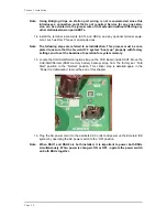
15. Locate the Cold Start/Normal option strap on the CCB Board inside KSU1. Move the
Cold-Start/Normal (RAM memory battery backup) strap from the factory set “Cold
Start” position to the “Normal” position. This critical step is detailed again in the
“Power Up Initialization” topic at the end of this chapter.
16. Plug the AC power cord into the dedicated AC outlet and power up the
Emerald ICE
system by operating the AC power switch to the “ON” position.
Note: When KSU1 and KSU2 are both installed, it is important to power both KSUs
simultaneously. When power is changed - ON or OFF - operate the power switch
on both KSUs together.
Summary of Contents for EMERALD ICE
Page 1: ...Emerald ICE Digital Key Telephone System TM Quick Installation Guide...
Page 6: ...vi NOTES...
Page 7: ...Section 1 Introduction...
Page 8: ...NOTES...
Page 12: ...NOTES...
Page 13: ...Section 2 System Design...
Page 14: ...NOTES...
Page 40: ...NOTES...
Page 41: ...Section 3 Installation...
Page 42: ...NOTES...
Page 54: ...Section 3 Installation Page 3 12...
Page 55: ...Emerald ICE Quick Installation Guide Page 3 13...
Page 57: ...Section 4 Basic Programming...
Page 58: ...NOTES...
Page 68: ...NOTES...
Page 69: ...Section 5 Programming Quick Reference Charts...
Page 70: ...NOTES...
Page 137: ......


