


Emerald ICE Quick Installation Guide
Page 3-5
Tools and Supplies
• Assemble the correct supplies and tools to install the
Emerald ICE
as it is intended.
• Use UTP (Unshielded, Twisted-Pair) three or four pair cable to run from the MDF (Main
Distribution Frame) to all station terminals (EKT, DSS Consoles and analog devices).
• Digital terminals only need one twisted pair to operate. (Additional pairs are always recom-
mended to allow for future potential uses e.g. Facsimile machines and modems.)
• Six conductor modular jack assemblies for all station terminals.
• Standard punch-down terminal block(s) (66Ml-50 type) as required.
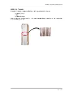
• Twenty-five (25) pair UTP cable fitted with male gender AMP-type connectors at one end
(typically referred to as “pig-tails”). The quantity of these cables is determined by the
equipment installed. The basic configuration requires two 25-pair cables.
• AC voltage surge/spike protector.
• Standard telephone hand tools and mounting hardware for the KSU(s), MDF backboard,
punch-down terminal block(s), modular jack assemblies, etc.
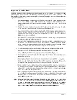
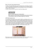
Preparing the Main Distribution Frame (MDF)
The Main Distribution Frame (MDF) is the point at which the KSU, terminal equipment, CO lines,
and miscellaneous equipment are connected to one another. It is extremely important that the con-
nections be made carefully and accurately. The MDF is where the KSU is located.
Assembling the MDF
Follow these steps to assemble the MDF.
1. Mount a sufficiently sized 3/4-inch plywood TMB (Telephone Mounting Board) at the
proper location for use as the MDF termination and equipment mounting board.
2. Plan the layout of all required MDF components allowing for expansion. This may
include: KSU1, KSU2, 66Ml-50 termination blocks, cable fastening hardware, and
miscellaneous third-party communications equipment (paging equipment, etc.).
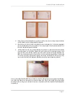
3. Locate the Telco provided CO/Centrex lines at the DEMARC (Demarcation) and
extend them to the MDF location.
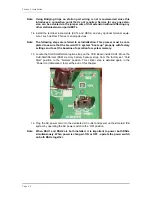
4. Locate a suitable, known-good earth ground preferably within 10 feet of the MDF and
route a #10 AWG grounding wiring from the point of grounding to the MDF for connec-
tion to the KSU. (See photo example.)
Install all terminal device wiring (telephone cabling) and route to the MDF location for
termination.
5. Mount all equipment and termination hardware as required to complete interconnec-
tion of terminal devices and KSU ports.
Summary of Contents for EMERALD ICE
Page 1: ...Emerald ICE Digital Key Telephone System TM Quick Installation Guide...
Page 6: ...vi NOTES...
Page 7: ...Section 1 Introduction...
Page 8: ...NOTES...
Page 12: ...NOTES...
Page 13: ...Section 2 System Design...
Page 14: ...NOTES...
Page 40: ...NOTES...
Page 41: ...Section 3 Installation...
Page 42: ...NOTES...
Page 54: ...Section 3 Installation Page 3 12...
Page 55: ...Emerald ICE Quick Installation Guide Page 3 13...
Page 57: ...Section 4 Basic Programming...
Page 58: ...NOTES...
Page 68: ...NOTES...
Page 69: ...Section 5 Programming Quick Reference Charts...
Page 70: ...NOTES...
Page 137: ......