background image

Emerald ICE Quick Installation Guide

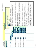
menu tree

_

bksp  save  chg

Code Sequences

(listed at the left side of 

every page/data item).

 Use: 

v

 to return to the Code Sequence entry screen


h

 to step back one menu level.


back

 - previous item this menu level


next

 - next item this menu level

show

-

show

this

menu

item

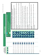
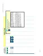
03

-

26

then press


save


03

-

27

then press


save


03

-

28

then press


save


03

-

29

then press


save


03

-

29

-

01

then press


save


03

-

29

-

02

then press


save


03

-

29

-

03

then press


save


03

-

29

-

04

then press


save


z

z

z

03

-

29

-

15

then press


save


03

-

29

-

16

then press


save


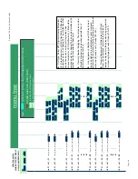
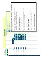
NULL

back  next  chg

AREA COD 1:NULL

back  next  chg

AREA PRE 1:NULL

back  next  chg

AREA COD 2:NULL

back  next  chg

COUNTRY CODE

back  next  show

LONG DIST PREFIX

back  next  show

NULL

back  next  chg

NULL

back  next  chg

AREA PRE 2:NULL

back  next  chg

z

z

z

AREA COD 8:NULL

back  next  chg

AREA PRE 8:NULL

back  next  chg

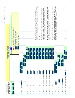
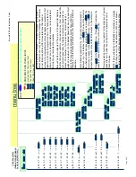
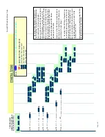
LOCAL AREA CODE

back  next  show

INTER. PREFIX

back  next  show


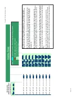
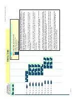
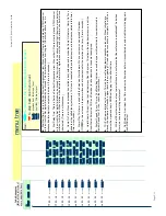
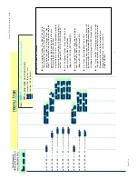
International Prefix: This is a Caller ID feature requirement. To dial back a number that is received 

from outside the USA, the International Prefix must be dialed (usually "011"). 


Country Code: This is a Caller ID feature requirement. This item is programmed with the country 

code where the ICE system will operate (usually "01" in the USA.) 


Long Distance Prefix: This is a Caller ID feature requirement. This item is programmed with the  

code required at the installed location to make long distance calls (usually "1".) When calls are received 

with Caller ID from a location that is long distance, this prefix is pre-inserted before the collected digits 

are dialed when the user has invoked CID Call Back.


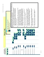
Local Area Code(s): This is a Caller ID feature requirement. This item is programmed with any 

A

rea Code(s) that can be dialed without a "1" as the first digit. These Area Code(s) identify numbers 

that will not be dialed with the Long Distance Prefix.

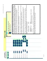
It is necessary to program the local Area Code and the code Prefix for each entry. Why? ...Caller ID 

digits received include the local Area Code, dialing the digits received MAY or MAY NOT require that 

the Area Code be output first to place the call. So...


The local Area Code is programmed into Local Area Code "1".


This causes the ICE system to ID this number as a local number 

          (do not dial Long Distance Prefix).


This also causes the ICE system to remove the Area Code from the digits

          received.


If the local Area Code received must be dialed to place a CID Call Back, the local


Area Code must be programmed into the Local Area Prefix "1" so that it is dialed.

Local Area Code entries are: Code/Prefix 1~8.

Page 5-12

Summary of Contents for EMERALD ICE

Page 1: ...Emerald ICE Digital Key Telephone System TM Quick Installation Guide...

Page 2: ...owever no responsibility is assumed by the Manufacturer for the use there of nor for the rights of third parties which may be affected in any way by the use thereof Any representation s in this docume...

Page 3: ...the telephone network the telephone company will notify you in advance that temporary discontinuance of service may be required If advance notice is not practical the telephone company will notify th...

Page 4: ...nufacturer s instructions 2 Verify that the power supply and associated A C powered equipment are connected to a properly grounded electrical supply and that power cords if used are unmodified 3 Verif...

Page 5: ...l Office Module 6 Circuits 2 9 Modem Module 2 10 4VAA Board 4 Port Voice Automated Attendant 2 11 Deluxe Model Telephone 2 12 Standard Model Telephone 2 14 DSS Direct Station Selection Terminal 2 15 E...

Page 6: ...vi NOTES...

Page 7: ...Section 1 Introduction...

Page 8: ...NOTES...

Page 9: ...he Emerald ICE supports Caller ID to Emerald ICE proprietary digital extensions and to third party Caller ID capable analog devices cordless telephones etc In addition to many standard features severa...

Page 10: ...e power failure port CO Line 1 One control contact LBC Gate External Page Control One external paging equipment interface Two serial ports PC RMP Programming Interface SMDR Station Message Detailed Re...

Page 11: ...Manual Convention Description Normal Used in body text throughout this manual Normal Italic Used in referencing sections telephone features and voice recordings or prompts Bold Italic Used in describi...

Page 12: ...NOTES...

Page 13: ...Section 2 System Design...

Page 14: ...NOTES...

Page 15: ...emplate The compact KSU weighs less than 20 pounds and is UL Listed If using 2 KSU s the first KSU or KSU1 is factory equipped with one 610 2 Board one CCB Common Control Board The second KSU or KSU2...

Page 16: ...SU2 for voltage regulation All system operation and logic voltages are produced at these boards Two fuses are provided on the power supply board one for ac enter over voltage protection and one for DC...

Page 17: ...the two horizontal connector sockets in the lower left corner of the CCB are for the Modem Module The connector socket labeled 2nd Cabinet is for connection to the KSU2 Base Board if that expansion i...

Page 18: ...ed to accomplish the task JP81 Internal External J81 is used to select the Music Channel 1 source The Emerald ICE provides a synthesized music source for music on hold in applications where no music s...

Page 19: ...noise filter The sixth CO Line port is equipped with CNG Fax Tone Detection circuitry If FAX tone is detected the call is routed to the analog port designated as the destination for fax calls Each di...

Page 20: ...SU2 operation LED located next to the power switch is tied to the CCB KSU1 LED Therefore when the LED next to the power switch is flashing the CCB KSU1 is active A long shielded cable is used to conne...

Page 21: ...oard is equipped with a Heartbeat LED that indicates processing activity on the PCB The 4SLT Board peripheral processor is operating when the Heartbeat LED is flashing The 4SLT Board provides DTMF rec...

Page 22: ...perations and two channels are used for the digital voice channel requirements The 12EKT is controlled directly from the 610 2 Board Base Board Each digital station interface is protected against circ...

Page 23: ...ule is shipped with four 4 mounting stand offs used to install the board into the KSU1 or KSU2 Each CO line circuit incorporates over voltage protection ring detector loop detector loop pulse dial rel...

Page 24: ...rom an off site location password verification required When installed the servicing technician uses the RMP and a modem in the PC to place a call to the site where the Emerald ICE is installed If one...

Page 25: ...a wonderful low cost voice processing system that can handle all call traffic or act as a backup to the primary answering system attendant The 4VAA is installed at J3 and J4 of the CCB The 4VAA provid...

Page 26: ...formation The display also enables the user to send and receive visual advisory and callback messages Users may select from six canned messages i e IN A MEETING OUT OF OFFICE or they may create a cust...

Page 27: ...Lamp to aid in user operations The lamp is dual color red green and indicates various modes of operation Messages Voice Messages Waiting Incoming calls distinctive for CO and intercom in use indicatio...

Page 28: ...ne features 14 programmable Feature DSS buttons dual color LED Headset Jack 8 fixed feature keys Mute Speaker Hold Transfer Con ference Feature Volume Up Volume Down and one Status Bar type message wa...

Page 29: ...any system Feature Code or Directory Number These but tons may be assigned for either system features operations or CO line access operations The DSS Console may be mounted in two positions Lower Pro...

Page 30: ...Integrated voicemail IVM Board Includes 8 channels with up to 120 hours of voicemail recording time It will be available as both Hard Disk and Flash based T1 PRI Board Future Feature VoIP Gateway Boar...

Page 31: ...rty conference circuits DISA circuits Any number of CO lines may be programmed for DISA operation 4VAA required for operation System Attendants 1 Attendant 1 Alternate per Tenant Group Tenant Groups 3...

Page 32: ...Stations Camped on to a station 1 Stations Camped on to a busy line 1 Message Executive Notification 6 preprogrammed 1 personal per station Message Executive Preprogrammed 6 preprogrammed 1 personal...

Page 33: ...impedance 1 8th inch phono jack Contact rating Option Module LBC 1A 30VDC 0 5A 90VAC 30Hz 1 8th inch phono jack External Page Port 0 dBm at 600 ohms 1 8th inch phono jack Environmental Data Operating...

Page 34: ...ses per second Pulse Make Break ratio 60 40 Internal Audible Signals Frequency Cadence CO Line Ringing Scheme 0 N A 300ms On 400ms Off 300ms On 4 seconds Off Scheme 1 N A 1 second On 3 seconds Off Sch...

Page 35: ...Off Scheme 3 follows ring cadence of Ring Scheme selected Scheme 4 follows ring cadence of Ring Scheme selected Scheme 5 follows ring cadence of Ring Scheme selected Scheme 6 follows ring cadence of...

Page 36: ...channels 4 VoIP channels 46 sta tions 6 SLT Only one VoIP gateway is allowed in cabinet 1 Only one 6CO board installation is allowed when T1 PRI is equipped in 2nd Cabinet The following combinations...

Page 37: ...e 6 boards base board is included by default for PCB interconnection Base 6CO 12EKT 6CO 12EKT or Base 6CO 12EKT 6CO 12 EKT 4SLT 4SLT or Base T1 PRI 12EKT 12EKT or Base T1 PRI 6CO 12EKT 12EKT or Base T...

Page 38: ...ation CO Extension 6CO Board 6CO 12EKTBoard 12EKT TI PRI Board 24 Channels 4SLT Board 4 Analog 6CO 1 12CO 2 4SLT 1 8SLT 2 12EKT 1 24EKT 2 604 1 1 608 1 2 612 1 1 616 1 1 1 620 1 1 2 624 1 2 628 1 2 1...

Page 39: ...25 2412 1 1 2416 1 1 1 2420 1 1 2 2424 2 1 2428 2 1 2432 2 2 3004 1 1 3008 1 2 3012 1 1 3016 1 1 1 3020 1 1 2 3024 1 2 3028 1 2 1 3032 1 2 2 Configuration CO Extension 6CO Board 6CO 12EKTBoard 12EKT T...

Page 40: ...NOTES...

Page 41: ...Section 3 Installation...

Page 42: ...NOTES...

Page 43: ...promote full ser viceability of the system and connections using proven techniques 6 Terminate extension cables on modular jack assemblies at the terminal locations 7 Mount the KSU S on the MDF backb...

Page 44: ...t the Emerald ICE system boots up properly with factory settings and to set the baseline of operation for system memory 15 Locate the Cold Start Normal option strap on the CCB Board inside KSU1 Move t...

Page 45: ...status of the main system processor During the first power up sequence Cold Start strap moved to Normal position default data factory program is loaded A series of flash rates occur during this proce...

Page 46: ...omputer with a hard disk drive This equipment cannot function in environments above 95 degrees Fahrenheit ambient tempera ture The MDF should consist of a 3 4 inch plywood TMB Telephone Mounting Board...

Page 47: ...Frame MDF The Main Distribution Frame MDF is the point at which the KSU terminal equipment CO lines and miscellaneous equipment are connected to one another It is extremely important that the con nec...

Page 48: ...ting template 1 Expansion Cabinet equipped with Base Board 1 hardware packet Open the carton s and verify that all items are complete and undamaged Remove all packing material and store for future use...

Page 49: ...allowed to rest in place on the mounting screws it will slip over the screw shanks until the top of the slot is reached Properly installed the KSU cover will swing open to the bottom or to the right s...

Page 50: ...g provided there A known good earth ground must be connected Examples of good earth grounds are Cold water pipe where the pipe is known not to have plastic or PVC insulators in line Ground Rod where t...

Page 51: ...ular ended crimping connectors and AMP type Male gender connectors These cables are then routed out of the KSU to the 66M1 50 blocks for termination and jumper wiring there The installer has choices w...

Page 52: ...required to be in position to comply with FCC regulations The 66Ml 50 is split into a left half and right half for wiring terminations Each row is conductive between the left two columns and the righ...

Page 53: ...66M1 50 Pinouts Emerald ICE boards equipped with 25 pair AMP type cable connectors are KSU1 612 Board 12EKT KSU2 Base Board Refer to the chart on pages 12 and 13 for pinout designations per cable pai...

Page 54: ...Section 3 Installation Page 3 12...

Page 55: ...Emerald ICE Quick Installation Guide Page 3 13...

Page 56: ...display will be visible on the Deluxe Telephones For a Standard telephone a dial tone will be heard 7 Enter the RMP programming mode and select RP Remote Control and perform a Soft ware Cold Start It...

Page 57: ...Section 4 Basic Programming...

Page 58: ...NOTES...

Page 59: ...th the digital telephone display Programming using the RMP is accomplished using the Microsoft Windows based application to program with check boxes drop down selection lists and fill in entries Delux...

Page 60: ...g Programming Calls Outgoing This would represent outgoing call programming The following table indicates the types of programming indicated by the first 2 digits in any given programming sequence Ind...

Page 61: ...screens are described briefly within the following subsections with specific pro gramming instructions provided in the following chapters of this manual All programming screen are accessed from the R...

Page 62: ...nformation Status Bars Two Status Bars are provided to present the real time status of RMP The upper part is Communi cation Port Status Bar and the other is Message Status Bar RMP Menu Hierarchy All p...

Page 63: ...e programming screens are shown below Basic descriptions and general usage for each of the subscreens shown below are provided in the subsections herein The specific programming instructions are provi...

Page 64: ...the maintenance features of the Emerald ICE These program ming screens are shown below Basic descriptions and general usage for each of the subscreens shown below are provided in the separate subsect...

Page 65: ...ntry screen will appear as shown below 3 Enter a password in the diaglogue box and click the OK button The default password is 8 spaces The following will be dislayed Local Connection 4 With the Local...

Page 66: ...or communications using the Baud Rate drop down list 8 Enter a 10 digit Modem Telephone Number in the Number field 9 Click on the Add to List button and the modem information will be displayed in the...

Page 67: ...save your changes to the Database Press N to abort changes and leave all data unchanged or Y to save changes If you selected Y for yes you will then be prompted File Exists Override If you select N fo...

Page 68: ...NOTES...

Page 69: ...Section 5 Programming Quick Reference Charts...

Page 70: ...NOTES...

Page 71: ...bksp show chg JAN 2 THU 2 50 EXT 403 is the default factory password Entering the TKS programming mode at a Deluxe Telephone is as easy as 1 2 3 left side Use the Code Sequence to jump to the databas...

Page 72: ...ree Tenant Groups Press chg change until the extension selected is in the Tenant Group desired Pickup Group There are eight Pickup Groups extension may pickup ringing calls at other extensions in thei...

Page 73: ...xt chg DROP CALL OUT N back next chg Drop Call Out Based on the Warning Time Out programmed shall the Emerald ICE disconnect outgoing calls made by this extension when the timer expires Drop Call In B...

Page 74: ...TRK 700 TNT 1 Y back next chg TRK 700 TNT 1 Y back next chg TRK 701 TNT 1 Y back next chg LINE ASSIGNMENT back next show DIR NO SWAPPING back next show PORT TYPE EXT back next chg Port Type Select EX...

Page 75: ...ameter only This will show any digital extension ports that are assigned to operate with the extension being programmed Wrong Number Destination This Pre programmed Call Forward feature assigns where...

Page 76: ...aling rules set up in Toll Restriction for the system Service Mode DAY Night Class ditto for the NIGHT Service Mode MOH Source Select MC1 MC2 or TONE MC1 can be either the Internal synthesized music G...

Page 77: ...onnect when a Loop Current interruption or Polarity Reversal is detected during a call holding and connected Is this Trunk to be assigned as a Private Trunk If so to which extension There are eight Ri...

Page 78: ...k Flash 0 1 3 0 seconds A K A 100ms 3000ms PBX Flash When a Hook switch Flash is invoked by a user on a trunk marked as Trunk Type PBX What is the duration of that Hook Flash 0 1 3 0 seconds A K A 100...

Page 79: ...is timer expires following the last ring signal detected on the CO circuit If your customer complains that ringing calls are not answered when they lift the handset increase this timer If your custome...

Page 80: ...ransfer destination continues as well If the timer expires a second time recall ringing begins at the programmed attendant extension as well Ringing continues until the call is answered Transfer Recal...

Page 81: ...detected the timer starts digits are sent at the end of the timer and after dial tone is detected Time is in milliseconds Camp On Time When an extension has called a busy extension and invokes the Cam...

Page 82: ...country code where the ICE system will operate usually 01 in the USA Long Distance Prefix This is a Caller ID feature requirement This item is programmed with the code required at the installed locati...

Page 83: ...which if any Tenant Groups are allowed to place intercom calls and CO Line transfers to extensions that are members of a different Tenant Group The Tenant to be programmed is input then for that Tena...

Page 84: ...er ECF receiving party may dial 0 to extend the call time the Talk Time is restarted He may also dial 0 disconnect the call Range 1 2 3 5 10 15 minutes Default 5 Voice Mail Dialing Ratio Tone Time Thi...

Page 85: ...is system wide timer determines how long a call will ring before the call is routed to the Preprogrammed Call Forward Destination Range 6 8 10 30 seconds Default 10 Ring Recognition Time This system w...

Page 86: ...receiving device This is necessary primarily for voice processors connected to ICE system analog ports This programming item is relevant only when the CID RPT MOD is set for DTMF operation Start Digit...

Page 87: ...e first and second ring signals from the Central Office ringing at the assigned telephones is delayed until this timer has expired time enough to collect CID data Proper ringing signal cadence of an o...

Page 88: ...Line is connected to the AA for processing Range 0 20 seconds Default 0 seconds 0 indicates that it will be answered immediately AA Ring No Answer How long should a call that has been transferred fro...

Page 89: ...ated Attendant continued AA Answering Position Day Mode The entry for this programming item will act as a destination for ringing while the system is in Service Mode Day Mode This destination is activ...

Page 90: ...Time to Answer After ringing signal has been detected on a CO Line how long should ring back tone be provided to the calling party before CO Line is connected to the DISA processor Range 0 20 seconds...

Page 91: ...a programming item will rarely ever be changed This setting matches the system interface port D A and A D converters The wrong setting results in garbled audio Range U_LAW A_LAW Default U_LAW Loop Bre...

Page 92: ...DB PSWD back next chg ALT DSS 1 NULL back next ALT DSS 2 NULL back next ALT DSS 3 NULL back next ALT DSS 4 NULL back next Database Password In this programming item the password used to access the cus...

Page 93: ...next chg REMINDER 7 NULL back next chg PLAY TIME 1 back next chg REMINDER 1 NULL back next chg REMINDER 2 NULL back next chg REMINDER 3 NULL back next chg SHOW TENANT _ bksp show chg LENGTH 4 back ne...

Page 94: ...Operator back next chg LINE 1 back next chg USER NAMES back next show SHOW TRUNK _ bksp show chg TRUNK NAMES back next show NULL back next chg SHOW EXT _ bksp show chg User Names Show Ext Input the e...

Page 95: ...er extension Six preprogrammed status messages are available for fast selection Each may be programmed here The factory defaults are shown Note one customizable status message is also available at the...

Page 96: ...CREASE 200 back next chg System Speed Number programming Programming may be done here It is also possible to program System Speed Dial bins via Attendant Administration When programming system speed d...

Page 97: ...back next show NULL back next chg ent Incoming Caller ID Name Assignment The ICE system provides for a programmed name association for those infrequent incoming calls with Caller ID that are received...

Page 98: ...hat hardware interface which allows the connection of ancillary Public Address Paging equipment This paging port may be assigned for simultaneous operation with the various system paging resources Tha...

Page 99: ...control contact is available in this system platform therefore this entry is always 1 Loud Bell Control Application The application can be assigned as L B Loud Bell for signaling system users that a t...

Page 100: ...used to access the modem E g calling into the ICE system from a remote local and connecting to the modem is accomplished by transferring he inbound modem call to this ICE modem directory number Range...

Page 101: ...nsions and to Trunks CO Lines Therefore Emerald ICE extensions have a specific dialing plan that governs their dialing priviledges in the Day Mode in the Night Mode and for the selected Trunk in the D...

Page 102: ...ht Mode on CO Lines with this COS Allowed Intervals These are the PSTN numbers that a user assigned Y for their COS will be able to dial When only one digit is entered only the first digit dialed is s...

Page 103: ...nt 01 t tenant 1 2 3 int interval number then press save X 05 01 t int 02 t tenant 1 2 3 int interval number then press save X 05 01 t int 03 t tenant 1 2 3 int interval number then press save X CLASS...

Page 104: ...k one menu level back previous item this menu level next next item this menu level h 05 01 t int 04 then press save X TRUNK COS back next show z z z CLASS 0 Y back next chg z z z CLASS 1 Y back next c...

Page 105: ...the index ID of Account Codes There are 600 possible Account Codes When inputing the ID three digits are required 001 600 These are the actual account codes If any are programmed they will appear her...

Page 106: ...enu level next next item this menu level h 05 02 01 then press save X 05 02 02 then press save X 05 02 02 acc 01 acc account code ID number then press save X 05 02 02 acc 02 acc account code ID number...

Page 107: ...O Lines transferred to the group and Intercom calls to the group are processed in the order inwhich they were received z Calls that enter a group are processed in a Queued fashion That is calls remain...

Page 108: ...p be associated UCD Group Attribute This setting will likely not change In the event that older technology RAN Recorded Announcement Devices are used for other UCD Group Overflow Announcements AND mor...

Page 109: ...L UCD Group Overflow 1 Destination This is where a caller in queue for an UCD Agent Member to become available answer will be routed when the Overflow 1 Timer has expired Range 401 464 230 253 Default...

Page 110: ...rflow 2 Timer has expired Range 401 464 230 253 Default NULL If the Overflow Destination is an extension Port Type Ext the queued UCD caller will remain in queue until the call is answered by that ext...

Page 111: ...h When the IVM Board is used these are the destination MB s for the UCD Overflow and Reroute Destinations When an ancillary VM system is connected via analog ports these DTMF codes are passed to that...

Page 112: ...il Group be associated VM Hunt UCD Group With which UCD Group shall this tenant VM Group be associated Range 0 24 Default 0 0 None VM Prefix Table Use the preceeding table to familiarize yourself with...

Page 113: ...iliarize yourself with in band DTMF digit codes that are sent to VM ports to identify call types and how the VM system should process the call VM Suffix Digits The Suffix digits are sent to the VM sys...

Page 114: ...r Phone Ring Position Day When the ICE system is in the Day Service Mode up to 6 extensions Hunt Groups UCD may be assigned to ring for the Door Phone Range 401 464 230 253 Default NULL Door Phone Rin...

Page 115: ...s number is 9 Any code up to 4 digits in length can be entered as the PBX Code The PBX Code programmed here flags the ICE system that a user has dial accessed a host PBX trunk toll restriction is then...

Page 116: ...number dialed for the appropriate digits necessary to place this call on a trunk in the Alternate Trunk Route E g If the local 1FB trunks in the selected trunk route are all busy when a call is place...

Page 117: ...the directory number of the selected trunk route to be swapped with another Trunk Applications Trunk Route Directory Swapping Swap With Enter the trunk directory number that this trunk route directory...

Page 118: ...ystem Application Ring Scheme Ten Ring Schemes are available Each has a unique applied ringing pattern to differentiate CO Line Trunk ringing from Intercom Ringing Use the following Chart to select th...

Page 119: ...cation Letter Type Eight Letter Types are available to display special characters entered using the 1 key for Names In Display Trunk Names and programmed Text Messages Select the desired Letter Type h...

Page 120: ...it programming Auto Log off will perform this function automatically Range 10 20 60 Default 20 System Application Log on Again This security data item prohibits access to database administration progr...

Page 121: ...ers to the Directory Number asignments of resources physical and software All Numbering Plan Directory Numbers can be changed to meet the needs of the application When Assigning directory numbers When...

Page 122: ...ed at the left side of every page data item Use v to return to the Code Sequence entry screen h to step back one menu level back previous item this menu level next next item this menu level show h thi...

Page 123: ...bksp save chg Code Sequences listed at the left side of every page data item Use v to return to the Code Sequence entry screen h to step back one menu level back previous item this menu level next ne...

Page 124: ...bksp save chg Code Sequences listed at the left side of every page data item Use v to return to the Code Sequence entry screen h to step back one menu level back previous item this menu level next ne...

Page 125: ...ill check to assure that there are no numbering conflicts If you have trouble entering a number as a leading digit it is likely that this number is a portion of a number being used by another resource...

Page 126: ...EXT HUNT GROUP back next show System Application Numbering Plan refers to the Directory Number asignments of resources physical and software The ICE system will check to assure that there are no numb...

Page 127: ...g Plan refers to the Directory Number asignments of resources physical and software The ICE system will check to assure that there are no numbering conflicts If you have trouble entering a number as a...

Page 128: ...xt show LEADING 2 NULL back next chg LEADING 3 NULL back next chg SYSTEM SPD NO back next show LENGTH 3 back next chg INDIV SPD NO back next show LENGTH 3 back next chg LEADING 1 5 back next chg Syste...

Page 129: ...k next chg LOUD BELL back next show LENGTH 3 back next chg LEADING 1 81 back next chg MUSIC SOURCE back next show LENGTH 3 back next chg LEADING 1 80 back next chg LEADING 2 NULL back next chg System...

Page 130: ...mber asignments of resources physical and software The ICE system will check to assure that there are no numbering conflicts If you have trouble entering a number as a leading digit it is likely that...

Page 131: ...ode Intercom Ring Voice is required at all telephone models to invoke this feature The ICE system will check for Suffix Code conflicts If you want to assign a code that is already assigned elsewhere y...

Page 132: ...g to other trunks or extensions Copy functions are possible one by one or by groups Note In the Extension Copy function all data is copied from the template extension to the destination extension EXCE...

Page 133: ...y digital telephone feature keys much faster This copy function is possible one by one or by groups When copying Feature Key data you must select a source this becomes the template So all data must be...

Page 134: ...4 then press save 08 14 01 then press save 08 14 02 then press save 08 14 03 then press save 08 14 04 then press save 08 14 05 then press save 08 14 06 then press save MINUTE 22 back next chg MONTH JA...

Page 135: ...whereby changes in ringing assignments operations take effect Time Switching can be set uniquely for each tenant group In Time Mode the Service Mode of the ICE system is assumed as Day Mode until Time...

Page 136: ...bksp save chg Code Sequences listed at the left side of every page data item Use v to return to the Code Sequence entry screen h to step back one menu level back previous item this menu level next ne...

Page 137: ......
Page 138: ...diranamerica com Email icesales tadiran us com USA Headquarters Tadiran Telecom Inc 4 Tri Harbor Court Port Washington NY 11050 Tel 1 516 632 7200 Fax 1 516 632 7210 Emerald ICE Quick Installation Gui...

Reviews: