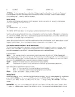
When the 2AIL1FL wing type is selected the brake can be mixed with each the elevator, aileron, or flaps. Adjust
each mix percentage as needed. Select a switch to turn the mix on/off..
PROGRAMMABLE MIXER:
Up to four programmable mixes can be set, with one channel being mixed to any one
or more channels. Control characteristics from the "input" channel will be passed to the "output" channel(s), such
as travel limits, exponential, etc. The output channel will still be able to function independently as if it were not
mixed with another channel, but once an adjustment is made to the input channel a resulting change will be seen
on the output channel as well. The mix level can be adjusted by percent. A switch can be assigned to turn this
mix on/off.
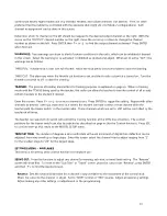
Enter the mixer screen. Move the cursor to select which mix to set and press ENTER.
The top line will show the mix number, with the cursor over the input channel, and the output channel to the right.
Press ENTER and
↑
+ or
↓
- to highlight and set the input channel.
The rate of the input channel to mix with the output channel can be adjusted for each the right and left side of the
input channel's center position. With the cursor next to RATE L, set the desired mix percentage. Repeat for RATE
R. Note the curve on the display's graph will adjust according to the percentages entered.
The amount of the input channel to be mixed can be offset by setting a percentage next to "OFFSET".
Assign a switch to control the mix in the CTRL line as explained earlier. Repeat the above procedures for each of
the four mixes that are to be configured.
RF OUTPUT:
The Rf output signal can be turned on or off. If changing any programming parameters in the radio
it's recommended to turn the Rf off so not to unnecessarily clutter the flying space with radio signals. Leave the
Rf output signal ON anytime the model is being controlled.
Enter this screen to perform a range check on the radio system, as fully explained on page xx.
TIMER:
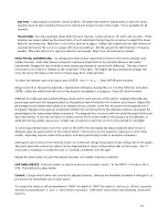
A timer is shown on the home screen, which can be configured in the TIMER menu. The timer can be set
to count up or down, and can be controlled by a user assigned switch. In addition, the timer can be controlled by
the throttle stick if desired.
To count UP as a stopwatch, leave the timer set to 00:00. To configure the timer to count DOWN, set a time other
than 00:00 with a maximum possible start time of 99:59. When used as a countdown timer, a set of tones will
sound at 00:10 and every second thereafter to warn that the timer is nearing the end. After reaching 00:00, the
timer will automatically begin counting up to help track how much longer the model was operational after the
timer ended.
A switch can be selected on the right side of the screen to turn the timer on / off. Place the box on-screen over
this setting and deflect the switch that will control the timer. In operation, the timer will be stopped when the
switch is in one position. Moving the switch to the opposite position will cause the timer to count. To reset the
timer, move the switch to the stop position and press the CLEAR button.
The timer can also be started and stopped by the throttle stick. Move the throttle stick to the minimum throttle
position. Place the box on-screen over this setting and press ENTER. When "Chose the control switch" displays,
move the throttle stick up from minimum throttle.
17


